Table 48 power failure transfer unit connections – Nortel Networks 1000M User Manual
Page 335
Connecting an attendant console
335
Physical slot
Logical slot
First TN...Last TN
Cable
Chassis
9
9
09 00...09 15
Card 9
Expander
10
10
10 00...10 15
Card 10
Expander
Note: Refer to the labels on the back of the chassis. See
Figure 106 "Cable connectors in a system
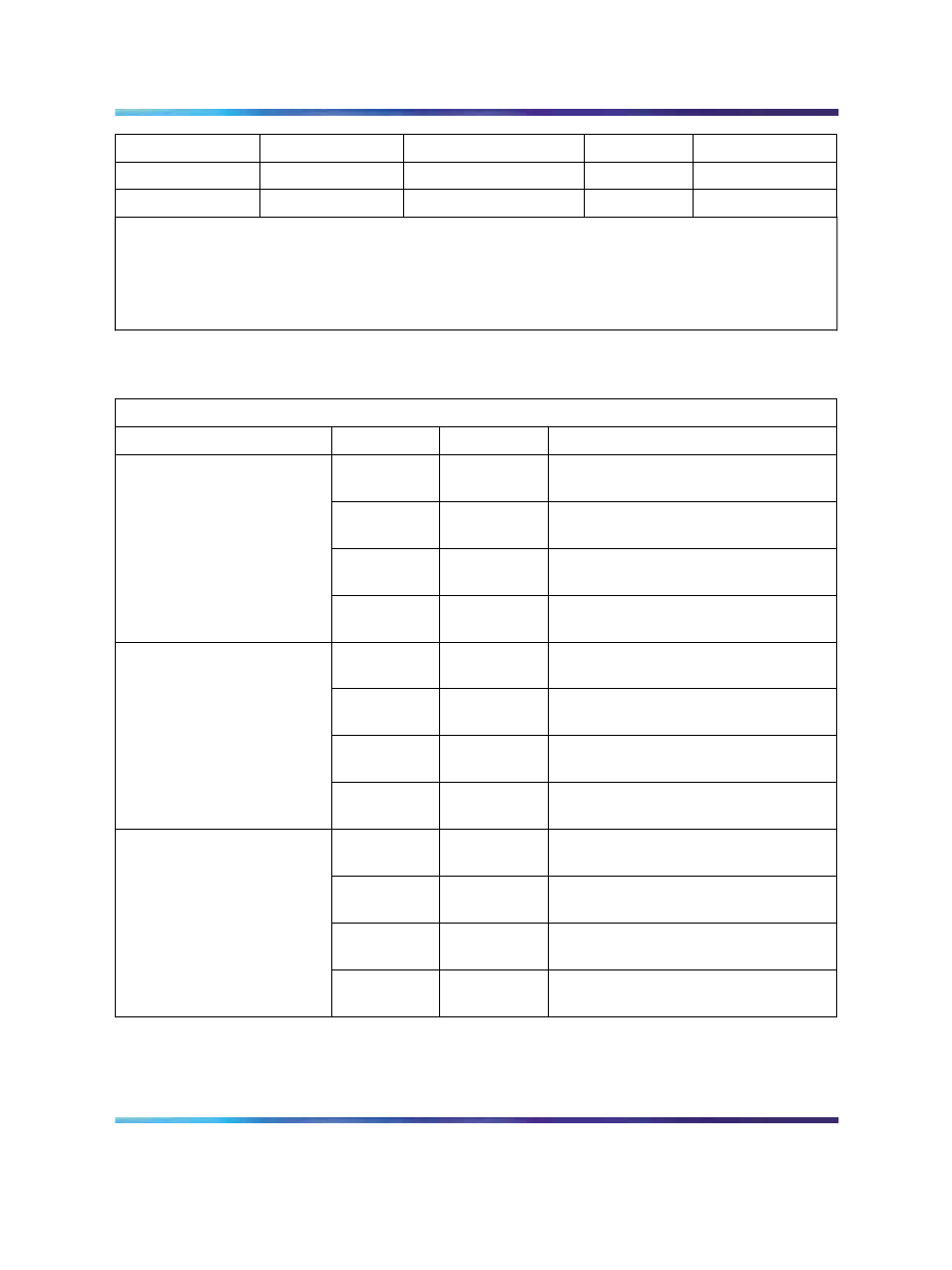
Table 48
Power Failure Transfer Unit connections
QUA6 J1 Cable
Function
Pair
Color
Connects to
5T
5R
W-S
S-W
Connect to the telephone
6T
6R
R-BL
BL-R
Connect to the telephone line card
7T
7R
R-O
O-R
Connect to the Central Office trunk
PFT 1
8T
8R
R-G
G-R
Connect to the trunk line card
9T
9R
R-BR
BR-R
Connect to the telephone
10T
10R
R-S
S-R
Connect to the telephone line card
11T
11R
BK-BL
BL-BK
Connect to the Central Office trunk
PFT 2
12T
12R
BK-O
O-BK
Connect to the trunk line card
13T
13R
BK-G
G-BK
Connect to the telephone
14T
14R
BK-BR
BR-BK
Connect to the telephone line card
15T
15R
BK-S
S-BK
Connect to the Central Office trunk
PFT 3
16T
16R
Y-BL
BL-Y
Connect to the trunk line card
Nortel Communication Server 1000
Communication Server 1000M and Meridian 1 Small System Installation and Commissioning
NN43011-310
01.04
Standard
Release 5.0
13 May 2008
Copyright © 2008, Nortel Networks
.