Figure 110 j1 cable labels, Table 31 control and power connections on cable j1, Procedure 43 installing the pftu – Nortel Networks 1000M User Manual
Page 230
230
Installing Power Failure Transfer Units
Procedure 42
Installing the PFTU
Step
Action
1
Mount the PFTU on the wall near the system cross-connect terminal
and secure it with four screws.
2
Install an NE-A25B-type 25-pair cable from connector J1 on the
faceplate of the PFTU to its assigned location at the cross-connect
terminal.
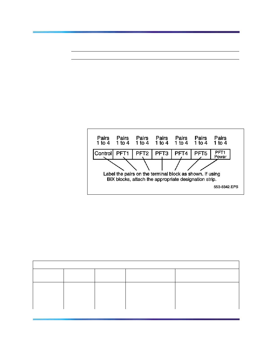
3
Label the pairs of the J1 cable on the cross-connect terminal block
as shown in
Figure 110 "J1 cable labels" (page 230)
Figure 110
J1 cable labels
4
Connect the PFTU power and control connections to the AUX
cable from the cabinet or chassis. See
power connections on cable J1" (page 230)
. For the location of the
Auxiliary port on the cabinet, see
Figure 111 "Auxiliary port location
. For the location of the AUX connector on
the chassis, see
Figure 111 "Auxiliary port location on cabinet"
.
Table 31
Control and power connections on cable J1
J1 Cable from QUA6 (see
Figure 113 "Power fail transfer" (page 234)
)
Function
Pair
Number
Pair
Color
Connects to
Cross-connect to
Control
1T
W-BL
(ALM)
Not used.
1R
BL-W
BRTN
W-BL 1-dot connection on
AUX cable from the cabinet
or chassis.
Nortel Communication Server 1000
Communication Server 1000M and Meridian 1 Small System Installation and Commissioning
NN43011-310
01.04
Standard
Release 5.0
13 May 2008
Copyright © 2008, Nortel Networks
.