Procedure 44 connecting sdi ports on the ssc card – Nortel Networks 1000M User Manual
Page 242
242
Installing and connecting SDI and Ethernet network interfaces
make sure only one baud rate switch is set to ON. Refer to
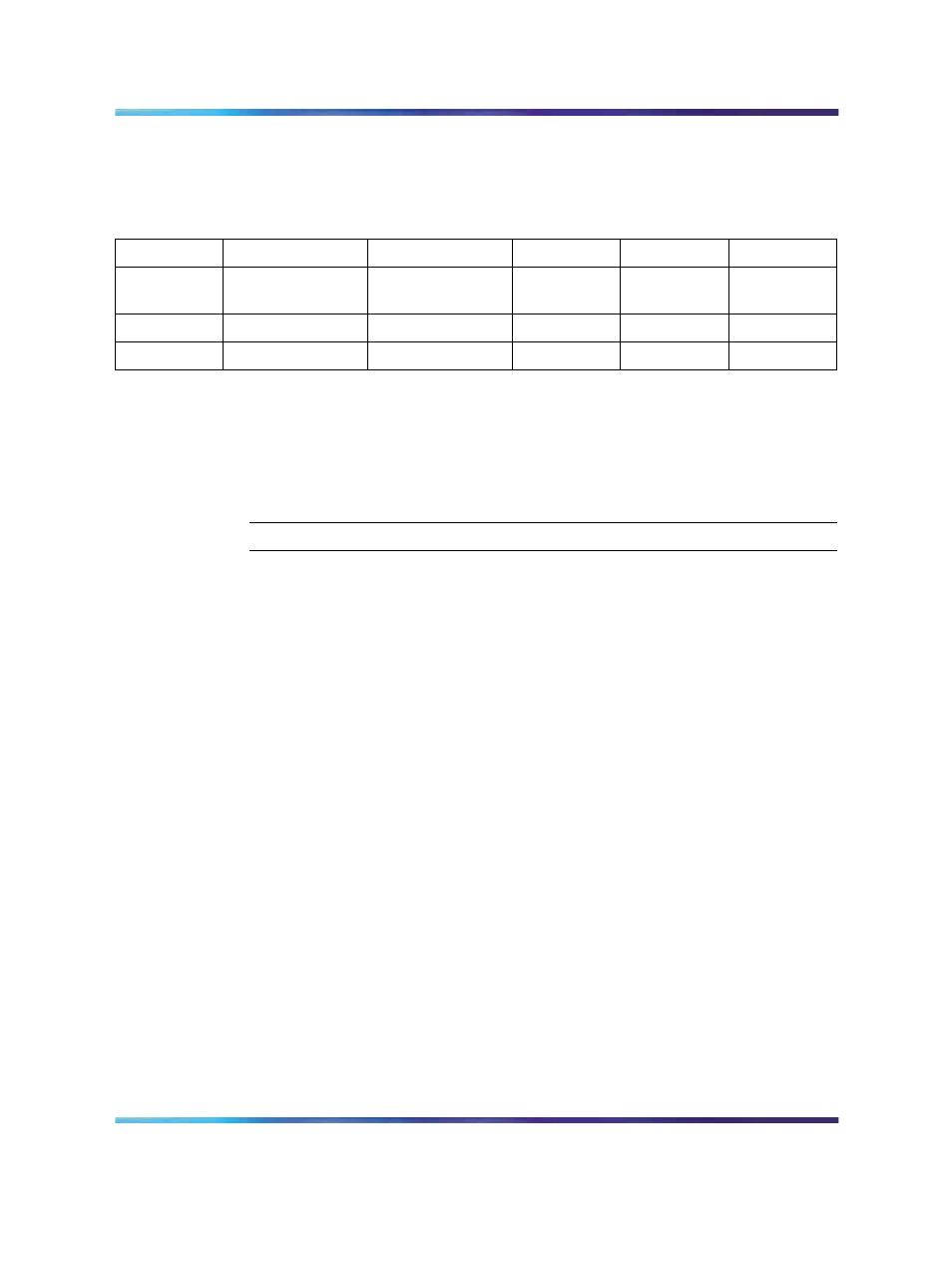
"Default port configuration for the NTDK20 SSC card" (page 242)
.
Table 34
Default port configuration for the NTDK20 SSC card
Port
Use
Baud rate
Data bits
Stop bits
Parity
0
MTC/SCH/BUG
Set by a DIP
switch
8
1
None
1
MTC/SCH/BUG
1200
8
1
None
2
MTC/SCH/BUG
1200
8
1
None
Procedure 43 "Connecting SDI ports on the SSC card" (page 242)
describes
how to connect a terminal, modems, and other devices, such as CDR
devices and additional TTYs, to the SSC card.
Procedure 43
Connecting SDI ports on the SSC card
Step
Action
1
Connect the NTBK48 3-port SDI cable to the 9-pin SDI connection
provided by the SSC card.
See
Figure 117 "SDI cable connection on the cabinet" (page 243)
for
the location of the SDI connection at the top of the main or IP
expansion cabinet.
See
Figure 118 "SDI cable connection on the chassis" (page 244)
for
the location of the SDI connection at the back of the chassis.
2
Connect the system terminal to the cable marked "port 1" on the
NTBK48 3-port cable.
A Modem Eliminator Adapter is required to connect the Small
System to a TTY terminal.
3
If the system is to be accessed remotely, connect the system modem
to the cable marked "port 0" on the NTBK48 cable.
Note 1: If port 0 is used, check the baud rate setting on the front
of the SSC card located in slot 0 of the Main Cabinet or Chassis.
If port 1 or 2 is used, the baud rate is configured in the system
software (LD 17).
Make sure that the rate is compatible with the modem.
Note 2: The CCBR feature works on all ports.
4
Connect the modem to an outside line.
Nortel Communication Server 1000
Communication Server 1000M and Meridian 1 Small System Installation and Commissioning
NN43011-310
01.04
Standard
Release 5.0
13 May 2008
Copyright © 2008, Nortel Networks
.