Figure 112 auxiliary connector on chassis – Nortel Networks 1000M User Manual
Page 233
PFTU installation
233
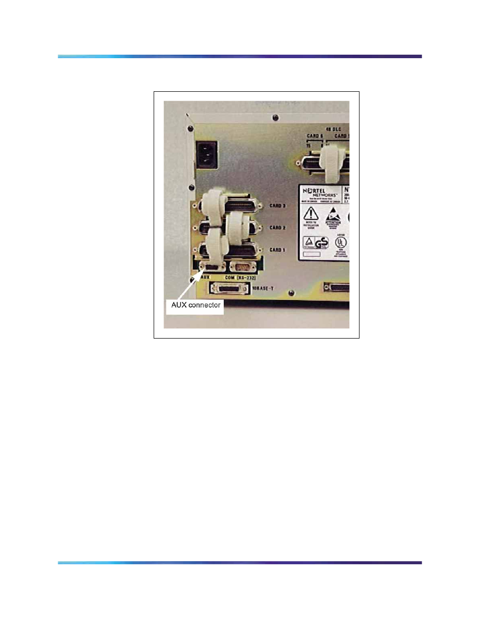
Figure 112
Auxiliary connector on chassis
5
Connect the attendant console to the PFTU:
•
attendant console 14 Tip (14T) to ground
•
3 Tip (3T) of PFTU to 11 Ring (11R) of attendant console (power
fail transfer switch)
•
attendant console 11 Tip (11T) to ground
Note: The AUX cable on the Chassis system does not provide
power to the M2250 attendant console. Two Digital Line Card
TNs or an attendant console power supply provide power to the
M2250 attendant console.
If power to the M2250 attendant console is not provided by two
Digital Line Card TNs, connect:
•
G-W of AUX to 8 Tip (8T) of attendant console (-15 V)
•
W-G of AUX to 7 Tip (7T) of attendant console (+15 V)
Nortel Communication Server 1000
Communication Server 1000M and Meridian 1 Small System Installation and Commissioning
NN43011-310
01.04
Standard
Release 5.0
13 May 2008
Copyright © 2008, Nortel Networks
.