Nortel Networks 1000M User Manual
Page 225
Connecting the cables
225
Table 29
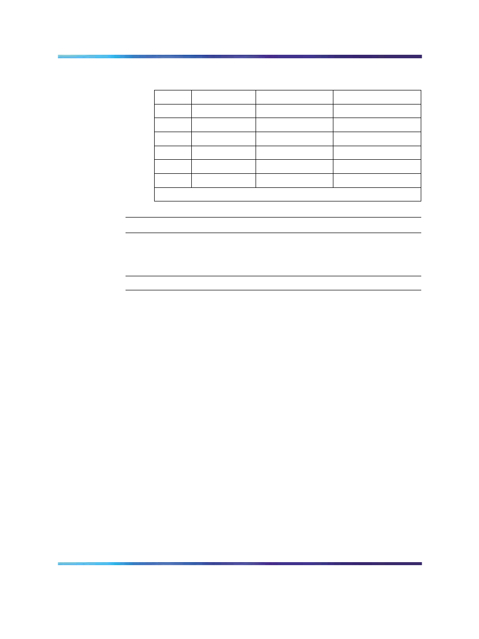
AUX cable terminations for the Cabinet system
Color
Wire number
Designation
Connection
W-BL
1
BRTN
to QUA6-J1 1R
BL-W
2
BRTN
to QUA6-J1 2R
O-W
3
-48V AUX (250mA)
to QUA6-J1 25T, 25R
W-O
4
PFTS
to QUA6-J1 2T
G-W
5
-15V AUX
Console power*
W-G
6
+15V AUX
Console power*
*Each AUX cable can provide power for only one console.
—End—
Procedure 41
Connecting the cables for the Chassis system
Step
Action
1
Loosen the Velcro straps at each connector you plan to use.
2
Connect a 25-pair cable to each of the connectors that will contain a
line or trunk card. Refer to the card slot assignment plan.
Make sure you tag both ends of each cable with the chassis and
connector numbers. See
Figure 106 "Cable connectors in a system
Nortel Communication Server 1000
Communication Server 1000M and Meridian 1 Small System Installation and Commissioning
NN43011-310
01.04
Standard
Release 5.0
13 May 2008
Copyright © 2008, Nortel Networks
.