Figure 113 power fail transfer, Table 32 pftu control lead signals – Nortel Networks 1000M User Manual
Page 234
234
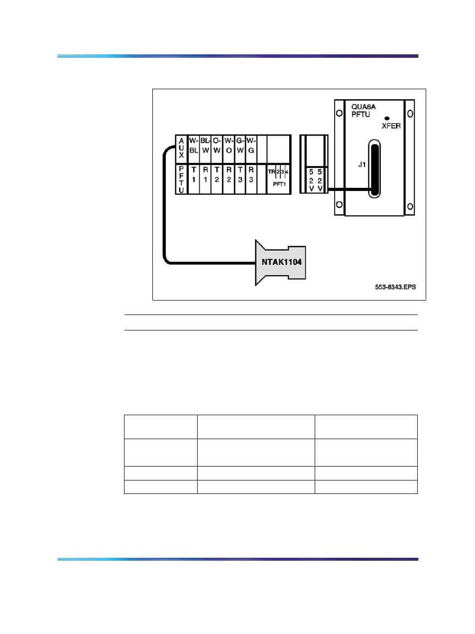
Installing Power Failure Transfer Units
Figure 113
Power fail transfer
—End—
PFTU control lead signals
To connect PFTUs from other manufacturers, use the information provided
in
Table 32 "PFTU control lead signals" (page 234)
Table 32
PFTU control lead signals
NTAK1104
AUX cable lead
Lead State when PFTU is
in non-transferred state
Lead State when PFTU
is in transferred state
BRTN
GROUND
GROUND
BRTN
GROUND
GROUND
-48V AUX
-48V DC (250 mA max.)
-48V DC (250 mA max.)
PFTS
OPEN
GROUND
Note 1: Refer to
Figure 111 "Auxiliary port location on cabinet" (page
for an illustration of where the Auxiliary cable connects to the
Cabinet system. Refer to
Figure 111 "Auxiliary port location on cabinet"
Nortel Communication Server 1000
Communication Server 1000M and Meridian 1 Small System Installation and Commissioning
NN43011-310
01.04
Standard
Release 5.0
13 May 2008
Copyright © 2008, Nortel Networks
.