Figure 106 cable connectors in a system cabinet – Nortel Networks 1000M User Manual
Page 224
224
Installing and connecting cross-connect terminals
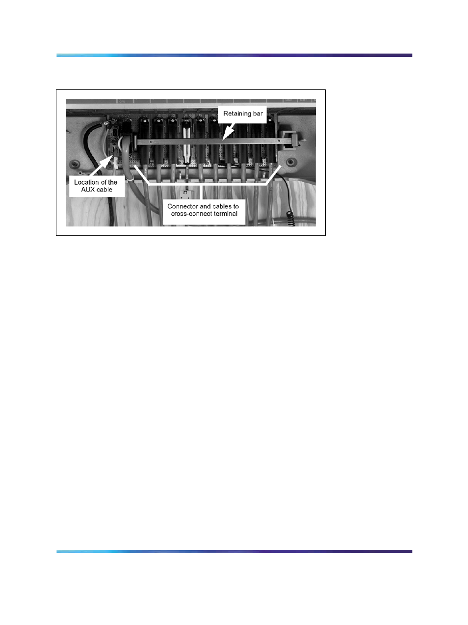
Figure 106
Cable connectors in a system cabinet
2
Using the card slot allocation plan, connect a 25-pair cable to each
of the connectors that will contain a line or trunk card.
Make sure to tag both ends of each cable with the cabinet and
connector numbers.
Note: Do not use the NE-A25B cable with the NTAK10, NTAK79,
or NTBK50 circuit cards.
3
Route the cables down through the opening at the bottom of each
cabinet.
4
Replace the retaining bar when you have connected all the cables
to the cabinet.
5
Terminate all the 25-pair cables installed at the cross-connect
terminal.
Label all the cables at the cross-connect terminal blocks according
to the card slot allocation plan.
6
Install the AUX cable on the lower 9-pin connector located on the left
side of the connector area in the lower part of each cabinet.
Terminate the AUX cable at the cross connector located on the
left side of the connector. See
Figure 106 "Cable connectors in a
Nortel Communication Server 1000
Communication Server 1000M and Meridian 1 Small System Installation and Commissioning
NN43011-310
01.04
Standard
Release 5.0
13 May 2008
Copyright © 2008, Nortel Networks
.