Figure 118 sdi cable connection on the chassis – Nortel Networks 1000M User Manual
Page 244
244
Installing and connecting SDI and Ethernet network interfaces
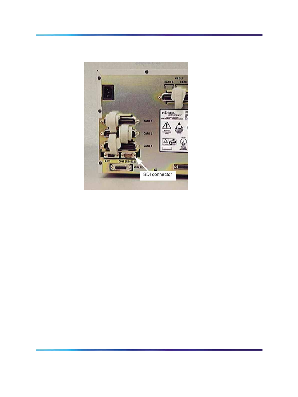
Figure 118
SDI cable connection on the chassis
NTDK23, NTDK25, and NTDK80 Fiber Receiver cards
The Fiber Receiver cards provide one SDI port per Expansion Cabinet
or Chassis.
The baud rate is set by a DIP switch on the card’s faceplate. Other
communication settings are identical to the port 0 configuration on the SSC
card (refer to
Table 34 "Default port configuration for the NTDK20 SSC
A Fiber Receiver card port must be configured using LD 17 before it can
be used to access overlays.
Note: Although all device numbers can be assigned to any cabinet or
chassis, TTY 0, 1, and 2 are usually assigned to the Main Cabinet or
Chassis. TTY 3, 4, 5, and 6 are typically assigned to the first, second,
third, and fourth Expansion Cabinets or Chassis respectively.
Procedure 44 "Connecting SDI ports to the Fiber Receiver card" (page
245)
describes how to connect the SDI ports on Fiber Receiver cards.
Nortel Communication Server 1000
Communication Server 1000M and Meridian 1 Small System Installation and Commissioning
NN43011-310
01.04
Standard
Release 5.0
13 May 2008
Copyright © 2008, Nortel Networks
.