Table 24 switch settings (ports 2 and 3), Table 25 jumper settings – Nortel Networks 1000M User Manual
Page 198
198
Installing optional circuit cards
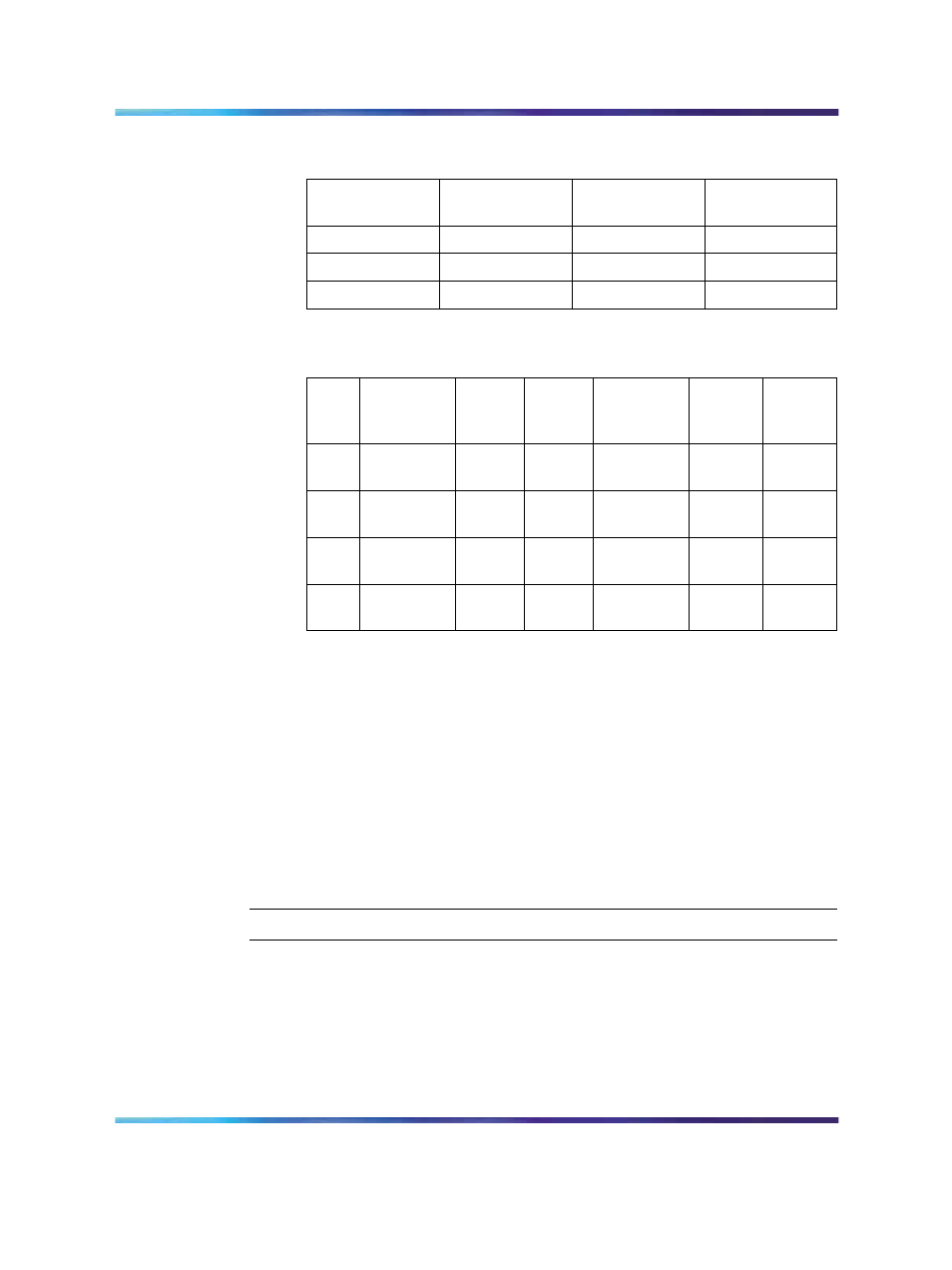
Table 24
Switch settings (Ports 2 and 3)
Port
2
Port
3
SW
1-3
SW
1-4
SDI
DCH
OFF
OFF
SDI
DPNSS
OFF
ON
—
ESDI
ON
ON
Table 25
Jumper settings
Port
Jumper
location
Stra
p for
DTE
Stra
p for
DCE
Jumper
location
RS422
RS232
Port
0
J10
C - B
B - A
Port
1
J7
J6
C - B
C - B
B - A
B - A
J9J8
C - B
C - B
B - A
B - A
Port
2
J5
C - B
B - A
Port
3
J4
J3
C - B
C - B
B - A
B - A
J2J1
C - B
C - B
B - A
B - A
2
Insert the card in its assigned slot.
You can install the NTAK02 SDI/DCH card in:
•
slots 1 through 10 of the cabinet
•
slots 1 to 3 of the chassis
3
Connect an NTAK19FB four port cable (or an NE-A25B cable) from
the corresponding connector at the back of the chassis. If you use an
NE-A25B cable, terminate this cable at the cross-connect terminal.
Because the NTAK19FB cable is equipped with connectors, it does
not require termination at the cross-connect terminal.
—End—
NT8D14 Universal Trunk card
The Universal Trunk card provides eight analog trunks which can function
in the modes shown in
Table 26 "NT8D14 Universal Trunk: modes and
.
Nortel Communication Server 1000
Communication Server 1000M and Meridian 1 Small System Installation and Commissioning
NN43011-310
01.04
Standard
Release 5.0
13 May 2008
Copyright © 2008, Nortel Networks
.