Rockwell Automation 8520-ARM2 9/Series CNC AMP Reference Manual Documentation Set User Manual
Page 741
Integrating a Linear Feedback Device
Appendix B
B-3
AMP Parameter
Value for Heidenhain
Distance--coded Marker*
Description
Larger Period for
DCM Scales
This parameter is used for scales with distance coded markers only. The
distance coded marker supported by the 9/Series must have equally
spaced odd and even markers. The distance between every odd marker
must be the same. The distance between every even marker must be the
same. For this parameter enter the larger of these two distances.
20.02 mM
Machine Pos. at
DCM Scale 0
This parameter is used for scales with distance coded markers only. This
parameter is similar to the homing parameter “Axis Position After
Homing”. The value entered here is used to redefine the control’s
interpretation of the actual zero marker on the scale. Use this parameter
to shift the machine coordinate system on your scale. The value entered
here becomes the actual value of the zero marker.
0
Teeth on Gear for
Pos. FB
This parameter should be set to one. Entering something other than one
will change the final Counts per Cycle calculation based on the ratio
between this parameter and “Teeth on Lead Screw for Pos. FB”.
1
Teeth on Lead
Screw for Pos. FB
This parameter should be set to one. Entering something other than one
will change the final Counts per Cycle calculation based on the ratio
between this parameter and “Teeth on Gear for Pos. FB”.
1
* Assumes Heidenhain model LS176 with:
Grating period = 20 M (i.e., 20,000 cts/cycle)
Small period = 20mM
Large period = 20.02mM
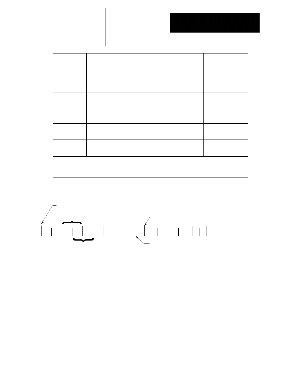
Figure B.1
Configuring a Scale with Distance Coded Markers
Smaller Period for DCM Scales (20.00)
Larger Period for DCM Scales (20.02)
Number of counts returned by scale in 1
Smaller Period defines Counts per Cycle.
Odd Markers
Even Markers
Assign this scale zero a new machine position
using “Machine Position at DCM Scale 0”