Rockwell Automation 8520-ARM2 9/Series CNC AMP Reference Manual Documentation Set User Manual
Page 594
Adaptive Feed & Depth Parameters
Chapter 32
32-8
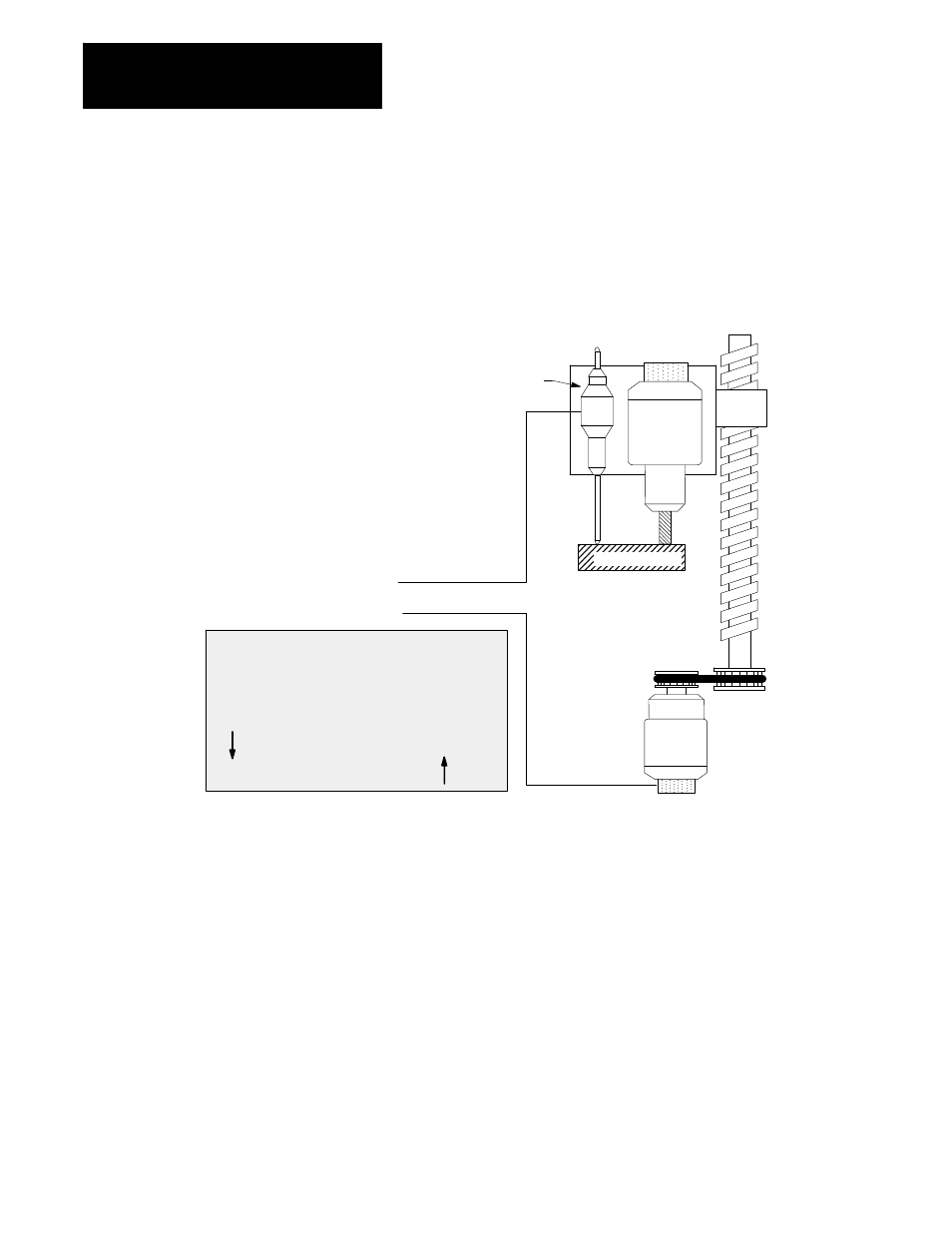
Assigning Trigger Direction and Feedback Direction
If you are using an adaptive depth probe, it is very important to make sure
that the probe’s position register (on the axis monitor page) is counting in
the same direction as the probe’s trigger direction. For example, if the
parameter Controlling Axis Trigger Dir is negative, then the probe
position register must count down as the probe is depressed.
Spindle
Motor
Z Axis
As the drill plunges into the drilling surface, both the
adaptive depth probe and the controlling axis encoder
must be returning feedback that is counting in the same
direction (both increasing or both decreasing).
Controlling
Axis Servo
Motor
Drilling Surface
Motor Feedback
Adaptive Depth
Probe Feedback
Controlling Axis Motion (Z)
Relative Adaptive Depth
probe deflection
In this example, even though the relative direction
of travel is in opposite directions, the feedback
must be wired such that both devices are
counting in the same direction.
Adaptive Depth Probe
Use the monitor pages (as discussed in your 9/Series Integration and
Maintenance manual) to see the direction the feedback is counting. You
can reverse the feedback on the adaptive depth probe either by re-wiring
the probe, or using the AMP parameter “Sign of Position Feedback”.