4 excess error – Rockwell Automation 8520-ARM2 9/Series CNC AMP Reference Manual Documentation Set User Manual
Page 177
Servo Parameters
Chapter 7
7-31
Function
This parameter places an upper limit on following error for a servo. When
the magnitude of the following error exceeds the value entered here, the
control goes into E-Stop. The error message EXCESS FOLLOWING
ERROR appears on the message line of the control.
ATTENTION: This parameter plays a significant role in
machine safety, as it can prevent damage and injury resulting
from mechanical or electrical failure of a servo.
The smaller the value for this parameter, the sooner the control detects a
servo problem and goes into E-Stop. However, too small a value here
interferes with normal axis motion.
Important: To avoid a Warning: ”SERVO AMP FE LIMITS
CORRECTED”: Inposition Band < Gain Break Point < Feedrate
Suppression Point
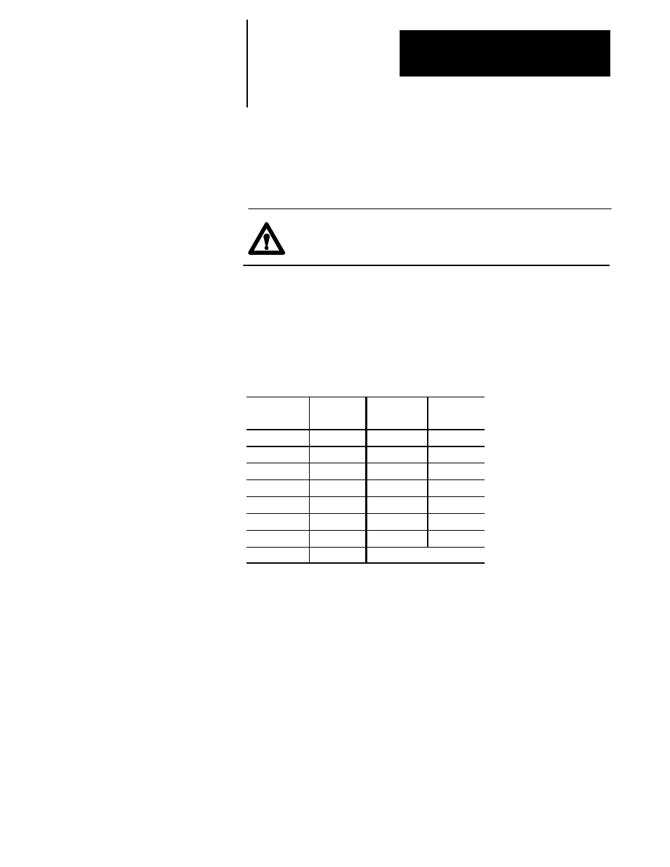
£ Excess Error
Axis
Parameter
Number
Axis
Parameter
Number
(1)
[1750]
(9)
[9750]
(2)
[2750]
(10)
[10750]
(3)
[3750]
(11)
[11750]
(4)
[4750]
(12)
[12750]
(5)
[5750]
(13)
[13750]
(6)
[6750]
(14)
[14750]
(7)
[7750]
(15)
[15750]
(8)
[8750]
Range
0 to 214.10000 mm or 0 to 8.42913 in. (linear axes)
0 to 1440.0000 degrees (closed--loop spindles)
0 to 214.00000 degrees (rotary axes)
Notes
This parameter must be set independently for each servo.
A typical value is 110% of the maximum following error expected during
operation of an axis. This can be determined by the following equation:
(maximum rapid speed) (1.1)
Min. Excess Error =
------------------------------------------
(Initial Gain) (1000) (Gain Break Ratio)
On closed--loop spindle applications, this parameter is only applied to the
servo while the spindle is orienting or tapping.
7.2.4
Excess Error