Configuring axes chapter 3 – Rockwell Automation 8520-ARM2 9/Series CNC AMP Reference Manual Documentation Set User Manual
Page 70
Configuring Axes
Chapter 3
3-6
Configuring Spindles
If you are using one or more spindles, refer to chapter 7 for information on
setting the parameters Spindle Type for Axis and Spindle Servo Board
for Axis.
You must configure the spindles in this order:
the first spindle axis is spindle 1
the spindle axis that follows the spindle 1 must be configured as
spindle 2
the spindle axis that follows spindle 2 must be configured as
spindle 3
Configuring Axes
1.
Press [F2] to pull down the Axis menu.
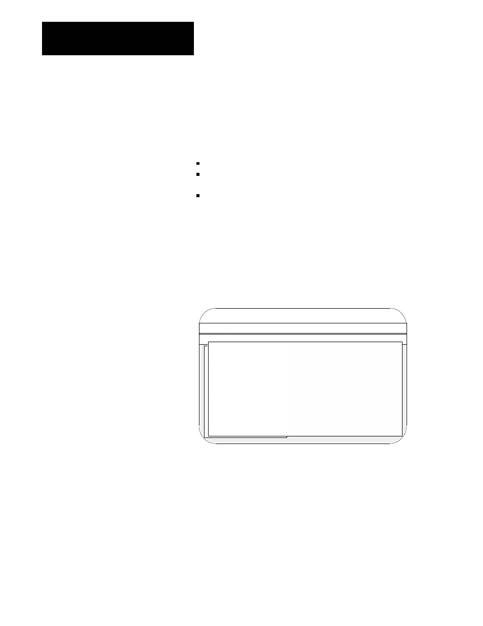
2.
Select the Configure Axis option (G).
The workstation displays this screen that shows the axes with their
currently assigned names:
Proj:
TEST
Appl:
AMP
Util:
Edit
F2-Project F3-Application F4-Utility
F5-Configuration
F1-File
F2-Axis
F3-Options
F4-Quick Edit!
Control Type : Mill
Axis :
X - linear
Axis Parameters
Home Parameters
Zone/Overtravel Parameters
Digital Servo Parameters
Analog Servo Parameters
Spindle 1 Parameters
Jog Parameters
Feedrate Parameters
Acc/Dec Parameters
CSS Parameters
Power-up G Codes
Cutter Comp/Tool Tip Radius
Paramacro Parameters
Axis Program Format
Page 1 of 2
File :
TEST
Select Axis to Configure:
----------------------------------------------------------------
Axis [1]
: X
linear
-
4 Axis Digital (8520) - Digital
(1)
Axis [2]
: Y
linear
-
4 Axis Digital (1394) - Digital
(2)
Axis [3]
: Z
linear
-
NONE
- NONE
(3)
Axis [4]
: U
unfitted
-
NONE
- NONE
(4)
Axis [5]
: V
unfitted
-
NONE
- NONE
(5)
Axis [6]
: W
unfitted
-
NONE
- NONE
(6)
Axis [7]
: C
unfitted
-
NONE
- NONE
(7)
Axis [8]
: A
unfitted
-
NONE
- NONE
(8)
Axis [9]
: B
unfitted
-
NONE
- NONE
(9)
Axis [10] : S
unfitted
-
NONE
- NONE
(a)
Axis [11] : S
unfitted
-
NONE
- NONE
(b)
Axis [12] : S
unfitted
-
NONE
- NONE
(c)
Axis [13] : S
unfitted
-
NONE
- NONE
(d)
Axis [14] : S
unfitted
-
NONE
- NONE
(e)
Axis [15] : S
unfitted
-
NONE
- NONE
(f)