3 velocity loop parameters – Rockwell Automation 8520-ARM2 9/Series CNC AMP Reference Manual Documentation Set User Manual
Page 206
Servo Parameters
Chapter 7
7-60
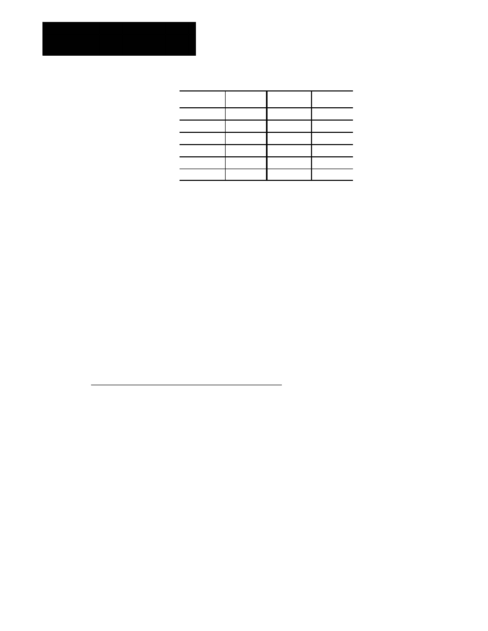
Axis
Number
Axis
Number
(1)
[1024]
(7)
[7024]
(2)
[2024]
(8)
[8024]
(3)
[3024]
(9)
[9024]
(4)
[4024]
(10)
[10024]
(5)
[5024]
(11)
[11024]
(6)
[6024]
(12)
[12024]
Range
--10.0000 to +10.0000 volts dc
Notes
This parameter must be set independently for each servo.
Important: This parameter should have a value that is less than that of the
parameter Analog Servo Pos. Voltage.
An example of this parameter would be if a 15 amp drive is combined with
a servo motor rated at 9 amps peak current, the servo card should probably
never exceed --6 volts to get the drive to output 9 amps to the motor. You
would set this parameter to --6 volts. The following equation is not valid
for servo systems that use the CNC to close the velocity loop.
--10 V (maximum servo card output) x 9 A (maximum rated motor current)
15 A (Drive output at 10V)
= --6 V (Analog Servo Positive Voltage)
The servo parameters in the sections that follow are available to configure
the velocity loop. The velocity loop is only configured for digital systems,
and analog systems that use a “Position/Velocity loop type”. These
parameters become available when the servo loop type is configured as
either “digital” or “position/velocity”.
Important: Digital systems must use the motor--mounted feedback device
(that comes pre-installed on the 8520 and 1326 digital motors) for velocity
feedback. This motor--mounted feedback must not be removed from the
motor or uncoupled from the motor shaft. Precisely oriented
motor--mounted feedback is necessary for accurate motor commutation on
digital systems.
7.3
Velocity Loop Parameters