Probing parameters, 0 chapter overview, Chapter – Rockwell Automation 8520-ARM2 9/Series CNC AMP Reference Manual Documentation Set User Manual
Page 579: Adaptive depth probing is discussed on page 32-1
Chapter
31
31-1
Probing Parameters
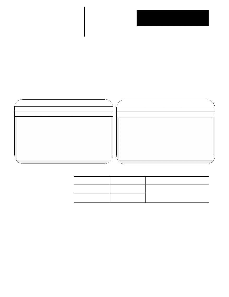
The workstation displays this screen when the “Probing Parameters”
group is selected:
Proj:
AMPTEST
Appl:
AMP
Util:
Edit
F2-Project F3-Application F4-Utility
F5-Configuration
F1-File
F2-Axis
F3-Options
F4-Quick Edit!
Type : Mill
AXIS: X
P1:
File :
TEST
Proj:
AMPTEST
Appl:
AMP
Util:
Edit
F2-Project F3-Application F4-Utility
F5-Configuration
When you select control type “Mill,” these parameters are displayed:
When you select control type “Lathe,” these parameters are displayed:
F1-File
F2-Axis
F3-Options
F4-Quick Edit!
Type : Lathe
AXIS: X
P1:
File :
TEST
- Probing Parameters -
Probe Length Compensation
:
0.00000 mm
Probe Radius Compensation
:
0.00000 mm
Probe Transition
:
Low to High
Approach Distance (R)
:
0.00000 mm
Tolerance Band Distance (D)
:
0.00000 mm
Approach Rate (E)
:
0.00000 mmpm
Probe Rate (F)
:
0.00000 mmpm
- Probing Parameters -
Probe Length Compensation
:
0.00000 mm
Probe Radius Compensation
:
0.00000 mm
Probe Transition
:
Low to High
If the application type is: and the control type is:
these parameters do not appear:
Mill/Lathe
Lathe
· Approach Distance (R)
· Tolerance Band Distance (D)
· Approach Rate (E)
Grinder
Cylindrical
· Tolerance Band Distance (D)
· Approach Rate (E)
· Probe Rate (F)
Adaptive depth probing is discussed on page 32-1.
31.0
Chapter Overview