5 default position offset – Rockwell Automation 8520-ARM2 9/Series CNC AMP Reference Manual Documentation Set User Manual
Page 389
Spindle Synchronization
Chapter 15
15-7
Function
This parameter denotes how much the controlling spindle’s marker leads
the follower spindle’s zero position during positional synchronization. The
zero point is determined by the marker and Spindle Marker Calibration
(page 12-13, 13-14, or 14-14). If a positional value is programmed in the
part program block, this default position offset value is ignored. This
parameter will also apply to any spindle orients that take place while
positional synchronization is active. For example, if a default position
offset parameter = 60.0, when the controlling spindle is oriented to 80
degrees, the follower spindle should be at 20 degrees if the synchronization
direction is normal, or --20 if the synchronization direction is reversed.
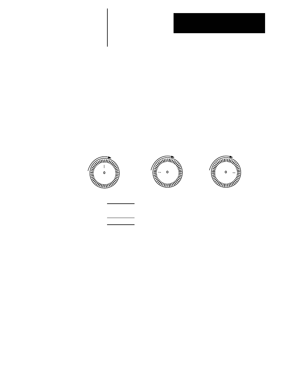
Figure 15.1
Aligning Controlling and Follower Encoder Markers
In this example, the controlling
spindle marker is positioned
at 0. The follower spindle’s
zero position is offset 90
degrees from the controlling
spindle’s position in normal
and reversed positions.
Controlling
Follower
Normal
Follower
Reversed
Parameter
Number
[594]
Range
0.000 to 360.000 degrees
Notes
This is a global parameter. The value set here applies to both spindles.
Threading with synchronization active will use the controlling spindle
marker. In a multiprocess 9/Series, the process not in spindle
synchronization mode will use the marker for the spindle configured for
that process.
15.5
Default Position Offset