2 velocity feedback type – Rockwell Automation 8520-ARM2 9/Series CNC AMP Reference Manual Documentation Set User Manual
Page 208
Servo Parameters
Chapter 7
7-62
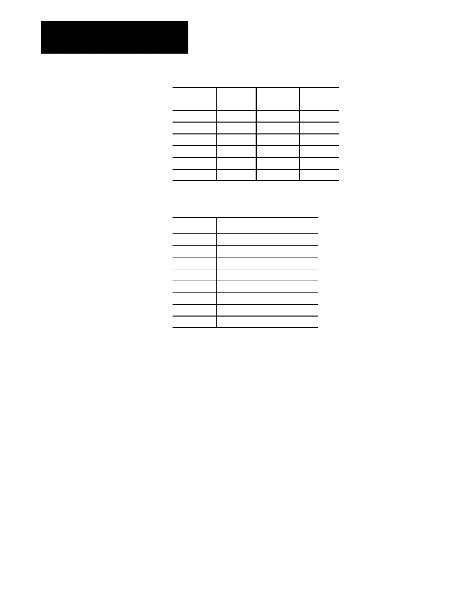
Axis
Parameter
Number
Axis
Parameter
Number
(1)
[1520]
(7)
[7520]
(2)
[2520]
(8)
[8520]
(3)
[3520]
(9)
[9520]
(4)
[4520]
(10)
[10520]
(5)
[5520]
(11)
[11520]
(6)
[6520]
(12)
[12520]
Range
Selection
Result
(a)
No Feedback
(b)
Feedback Connector J1 or CN5
(c)
Feedback Connector J2 or CN6
(d)
Feedback Connector J3 or CN7
(e)
Feedback Connector J4
(f)
Feedback Connector J9
(g)
Feedback Connector J10
(h)
Feedback Connector J11
Notes
This parameter must be set independently for each servo.
Function
The standard servo feedback configuration uses one feedback device for
both positioning and velocity data. If this is the case on your system, this
parameter must be set to the same value as the parameter Position
Feedback Type. Refer to this chapter’s overview for an example of a
system that uses two feedback devices for the same servo and may require
a different feedback type to be selected here.
Though the analog servo interface does not support a separate feedback
device for the velocity loop, you must still configure these velocity loop
parameters including Velocity Loop Feedback Port, Velocity Loop
Feedback Type, Velocity Feedback Counts/Cycle, and Sign of Velocity
Feedback. These parameters must be set to the same values as their
positioning loop counterparts.
7.3.2
Velocity Feedback Type