Cutter comp/tool tip radius, 0 chapter overview, Chapter – Rockwell Automation 8520-ARM2 9/Series CNC AMP Reference Manual Documentation Set User Manual
Page 501
Chapter
23
23-1
Cutter Comp/Tool Tip Radius
This chapter describes the Cutter Compensation and Tool Tip Radius
Compensation (TTRC) parameters. This lets the part programmer program
the path the tool follows in terms of the tool’s center or gauge point
without regard to the diameter or tool-tip radius.
The Cutter Compensation and TTRC parameters are broken into
two sections:
Parameter:
Page:
Compensation basic setup
23-2
Compensation error detection
23-13
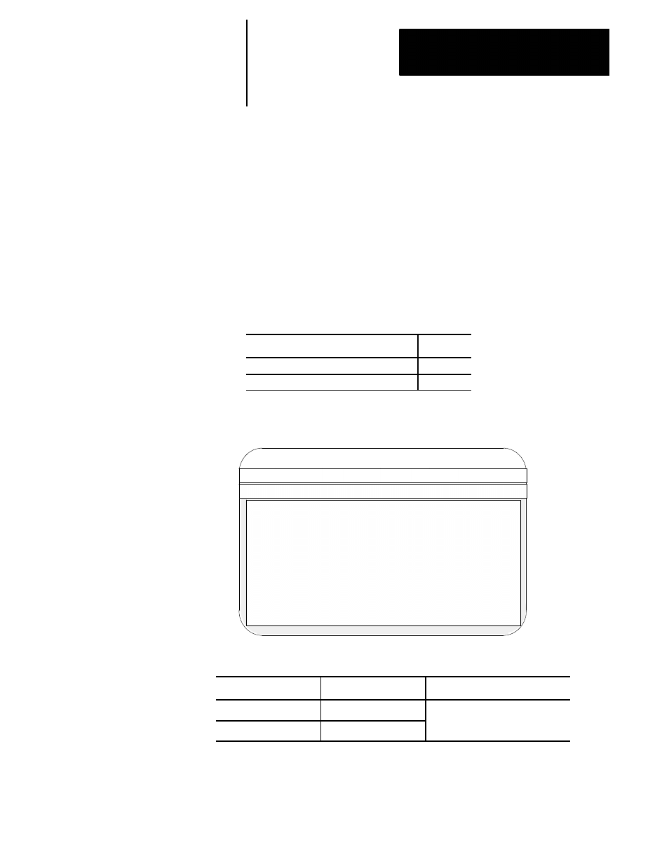
When you select “Cutter Comp/Tool Tip Radius” from the main menu
screen, this screen becomes available:
Proj:
AMPTEST
Appl:
AMP
Util:
Edit
F2-Project F3-Application F4-Utility
F5-Configuration
F1-File
F2-Axis
F3-Options
F4-Quick Edit!
Control Type : Mill
Axis :
X - linear
File :
TEST
- Cutter Comp/Tool Tip Radius -
Cutter Compensation Type
:
Type A
Defines offset as Diam. or Rad
:
Diameter
Min Block generation length
:
0.01000 mm
Max number of non-motion blks
:
5
Interference detection
:
Enabled
Reverse comp motion detection
:
Enabled
M word to disable Interference
:
800
M word to enable Interference
:
801
Minimum feed reduction %
:
80 %
Corner override angle
:
90 Degree
Corner override distance (DTC)
:
2.54000 mm
Corner override distance (DFC)
:
2.54000 mm
Corner override %
:
80 %
These parameters also appear if the application type is Grinder and the control type is Surface.
If the application type is: and the control type is:
these parameters do not appear:
Mill/Lathe
Lathe
Defines offset as Diam. or Rad
Grinder
Cylindrical
For Dual Processing controls, these parameters are global and can not be
set per process. The values set apply to all processes.
23.0
Chapter Overview