Range – Rockwell Automation 8520-ARM2 9/Series CNC AMP Reference Manual Documentation Set User Manual
Page 165
Select this option for TB2 of the 3 or 4-axis
analog servo card, TB2 of the 4-axis digital
servo card, TB3 of the 9/230, or CN8 of the
3-axis digital servo card. Note CN8 is only
available for spindles.
Servo Parameters
Chapter 7
7-19
Important: On 9/260 and 9/290 systems all axes with feedback must use an
Output Port Number, a Position Loop Feedback Port, and a Velocity Loop
Feedback Port from the same servo module.
Axis
Parameter
Number
Axis
Parameter
Number
(1)
[1540]
(9)
[9540]
(2)
[2540]
(10)
[10540]
(3)
[3540]
(11)
[11540]
(4)
[4540]
(12)
[12540]
(5)
[5540]
(13)
[13540]
(6)
[6540]
(14)
[14540]
(7)
[7540]
(15)
[15540]
(8)
[8540]
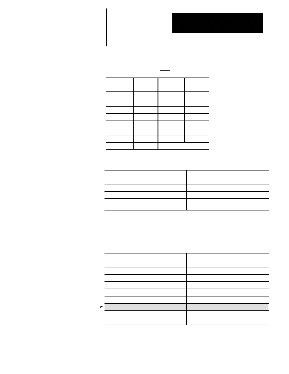
Important: For 1394 Serial Drives, use Amplifier Slot Number and refer to
the following table to determine if this parameter is valid with your system type.
If you have this type of axis:
define your 1394 drive amplifier output ports
with this parameter:
Open--loop analog spindle
Not allowed via 1394 serial drives
Closed--loop analog servo
Not allowed via 1394 serial drives
Closed--loop digital servo or digital spindle
Axis module 1, 2, 3, or 4
(to associate the axis to axis module amplifier)
For more information on ID of Amplifier Rack and its association with
1394 Serial Drives, refer to page 7-93.
Range
If you are not configuring an analog spindle
(1326 digital spindle use this column)
If you are configuring a spindle
(excluding 1326 digital spindles)
(a) No Output
(a) No Output
(b) Output Connector J1/CN2/Ax Mod1 (9/440)
(b) Analog Output Connector J1
(c) Output Connector J2/CN3/Ax Mod2 (9/440)
(c) Analog Output Connector J2
(d) Output Connector J3/CN4/Ax Mod3 (9/440)
(d) Analog Output Connector J3
(e) Output Connector J4/Ax Mod4 (9/440)
(e) Analog Output Connector J4
(f) Analog Out Conn TB2 or TB3 (9/230)
(f) Analog Out Con TB2/TB3 (9/230)/CN8
(g) Analog Out Conn TB2 (9/440)
(g) Analog Out Conn TB2 (9/440)
(h) Analog Out Conn TB3 (9/440)
(h) Analog Out Conn TB3 (9/440)