15 teeth on gear for position feedback – Rockwell Automation 8520-ARM2 9/Series CNC AMP Reference Manual Documentation Set User Manual
Page 200
Servo Parameters
Chapter 7
7-54
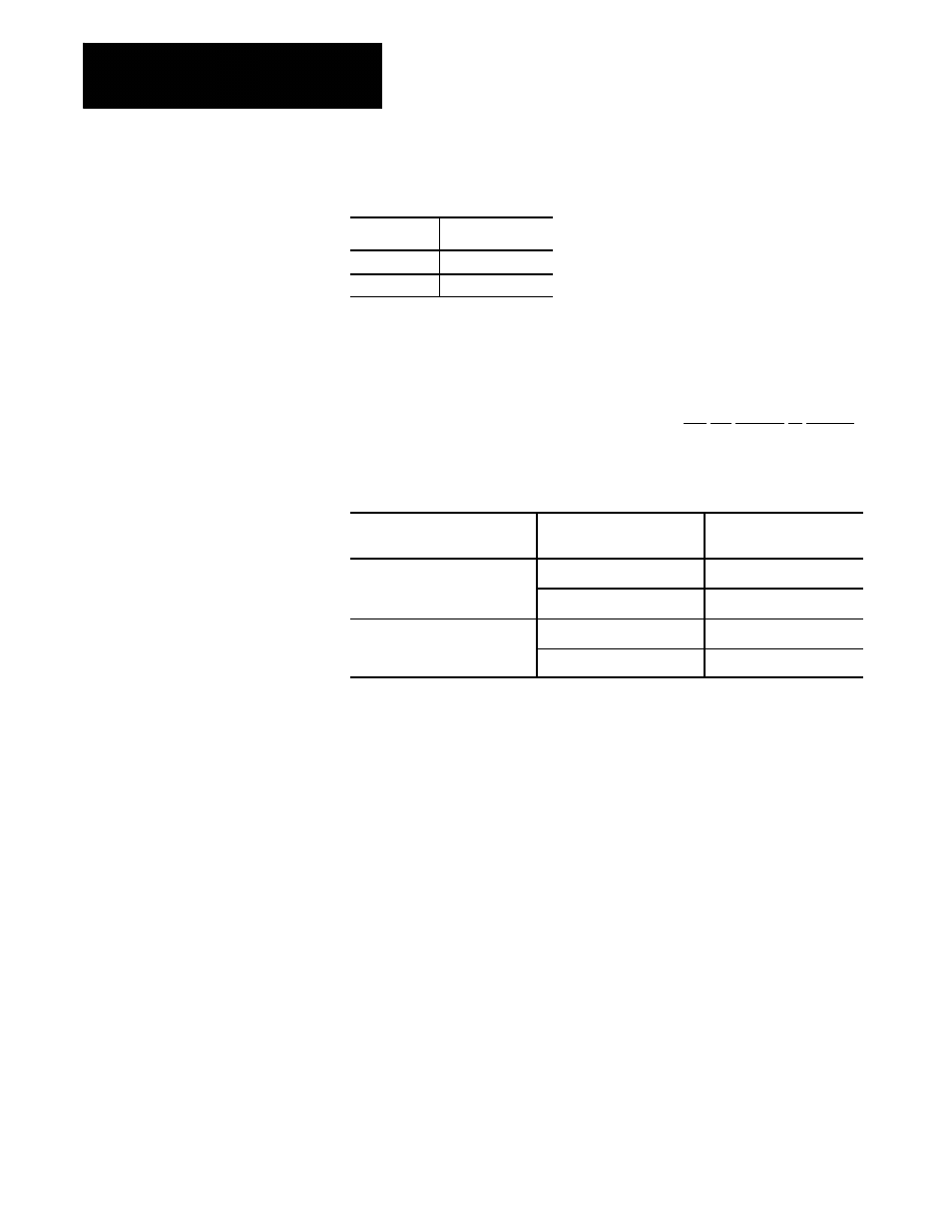
Range
Selection
Result
(a)
Plus
(b)
Minus
Notes
This parameter must be set independently for each servo.
After installing and wiring the feedback device, put the control in E-Stop,
and set the axis display to monitor feedback. Manually rotate the
feedback device, noting axis direction and whether the feedback is
counting negative or positive.
If the axis is moving in the
direction defined as:
and if the feedback is
counting:
then, for the Sign of
Position Feedback, enter:
positive
up
PLUS
down
MINUS
negative
down
PLUS
up
MINUS
Function
If you are using the same physical device for both the velocity loop and
position loops, then the value entered for this parameter should be the same
as the value entered for the parameter Teeth on Lead Screw for Vel FB.
If you are using a nonmotor--mounted position feedback device (connected
to a separate feedback port than the velocity feedback), enter the number of
teeth on the gear or gearbelt pulley attached to the feedback device. This
number is used in conjunction with the parameter Teeth on Lead Screw
for Pos FB to calculate the gear ratio from the position feedback device to
the lead screw (number of lead screw revolutions that occur between
position feedback device revolutions). The control then uses this ratio
combined with the entered Lead Screw Thread Pitch and Position
Feedback Counts/Cycle to determine the number of feedback counts that
occur per revolution of the lead screw.
Important: If configuring a linear position feedback device (excluding
distance--coded marker systems) use the parameters Position Feedback
Counts/Cycle and Lead Screw Thread Pitch to enter the number of
counts returned by the device per revolution of the lead screw. The ratio
7.2.15
Teeth on Gear for
Position Feedback