Rockwell Automation 8520-ARM2 9/Series CNC AMP Reference Manual Documentation Set User Manual
Page 736
Tuning a Digital or Tachless Analog System
Appendix A
A-14
Continue raising velocity integral gain and lowering velocity
proportional gain until an oscillation occurs that can not be stabilized
by adjusting the velocity proportional gain. This “bounded”
oscillation will appear different than the velocity overshoot shown
previously. This will be a continuous harmonic oscillation either
when the servo reaches speed or when the servo is at rest.
This bounded oscillation is a result of the integral gain being too
high. You should first notice the oscillation during motion at the
commanded velocity. If you continue raising the velocity integral
gain you will see oscillation when the axis is at rest (no commanded
velocity).
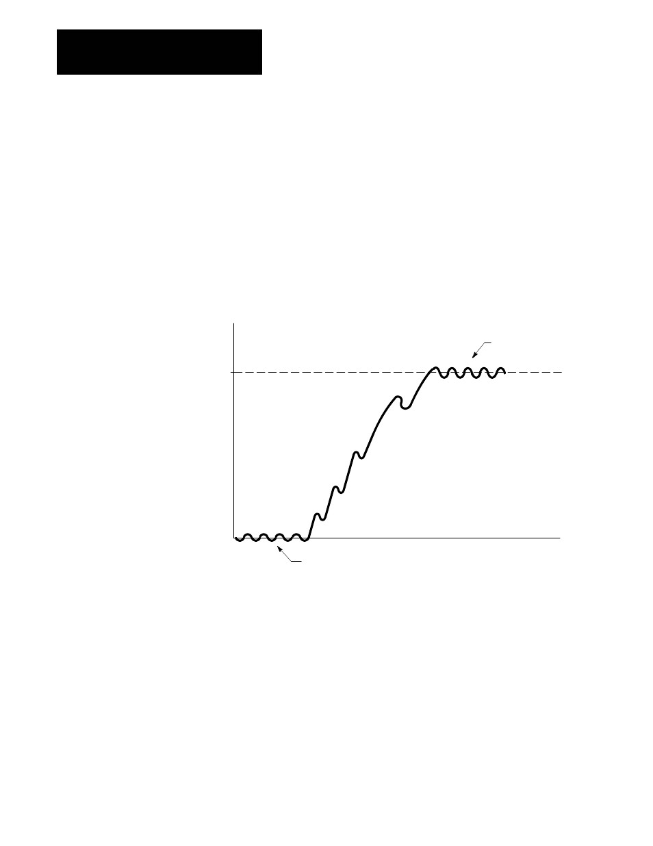
Figure A.2
Acceleration Curve Showing Axis Oscillation from Integral Gain too High
Time
Velocity
Commanded Velocity
Oscillation at commanded
velocity
Oscillation at zero commanded velocity.
Zero Commanded Velocity
7.
Once you have found the value of velocity integral gain at which the
axis just starts to oscillate, lower its value until the oscillation just
stops. Adjust the velocity proportional gain to a point just below
where over shoot occurs. This will be your optimal values for that
axis and will give you the best servo performance.
8.
Upload or manually enter these values into your ODS AMP file for
backup.
9.
Repeat this procedure until all axes are tuned.
10. Remove the strip chart recorder and turn the DAC monitor feature off
in patch AMP.