3 adapter rack size – Rockwell Automation 8520-ARM2 9/Series CNC AMP Reference Manual Documentation Set User Manual
Page 603
Remote I/O Parameters
Chapter 33
33-3
Function
This parameter specifies the logical rack size of the remote I/O rack as it
appears to the scanner. This is not the same as the physical rack of the
control. The scanner sees a full rack to be 128 I/O points (eight 16-bit
words). 128 I/O points is the maximum number of discrete points you can
assign to a 9/Series control through remote I/O.
Axis
Parameter Number
Mill/Lathe
Grinder
All
[142]
[147]
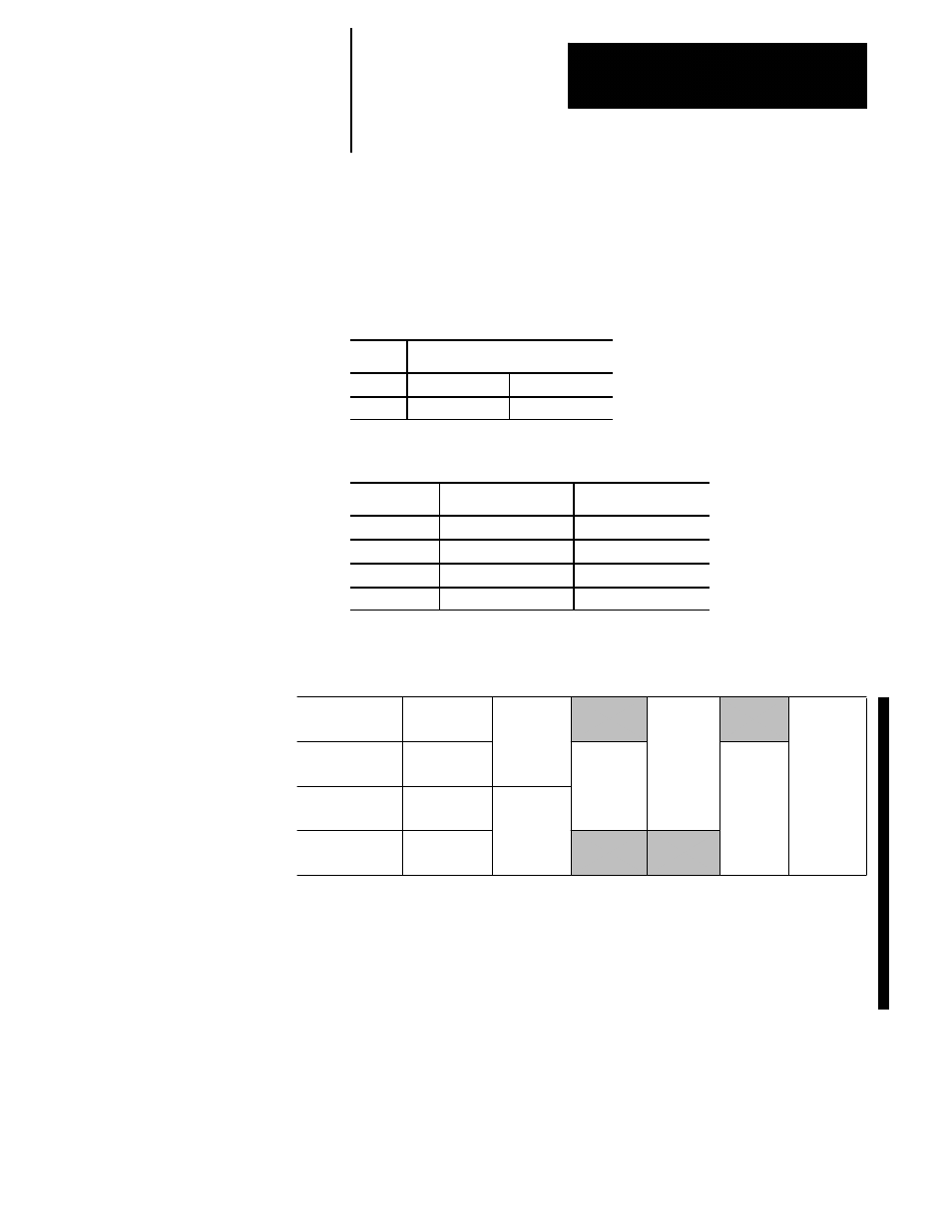
Range
Selection
Result
I/O points
(a)
1/4 rack
32 inputs/32 outputs
(b)
1/2 rack
64 inputs/64 outputs
(c)
3/4 rack
96 inputs/96 outputs
(d)
full rack
128 inputs/128 outputs
Notes
Every quarter rack equates to two input and two output words in PAL.
$RMI1
$RMI2
$RMI3
$RMI4
$RMI5
$RMI6
$RMI7
$RMI8
$RM01
$RM02
$RM03
$RM04
$RM05
$RM06
$RM07
$RM08
SQ0 Quarter
SQ1 Quarter
SQ2 Quarter
SQ3 Quarter
Half
Half
3/4
3/4
Full Rack
Half
The actual words used is dependant on your setting of the parameter
“Adapter Start Module Group”. With the “Adapter Start Module Group”
parameter you select the starting address for your 1/4, 1/2, 3/4 or full I/O
rack. 1/4 racks can start at any of the four quarters. 1/2 racks must start at
either the SQ0, SQ1, or SQ2 quarters. 3/4 racks must start at either SQ0 or
SQ1 quarters. Full racks must always start at the SQ0 quarter.
The PLC system installer may be able to help you determine this value.
33.3
Adapter Rack Size