Rockwell Automation 8520-ARM2 9/Series CNC AMP Reference Manual Documentation Set User Manual
Page 734
Tuning a Digital or Tachless Analog System
Appendix A
A-12
Find the Maximum Velocity Proportional Gain value:
1.
Activate and execute your tuning part program and record the servos
velocity response with the strip chart recorder.
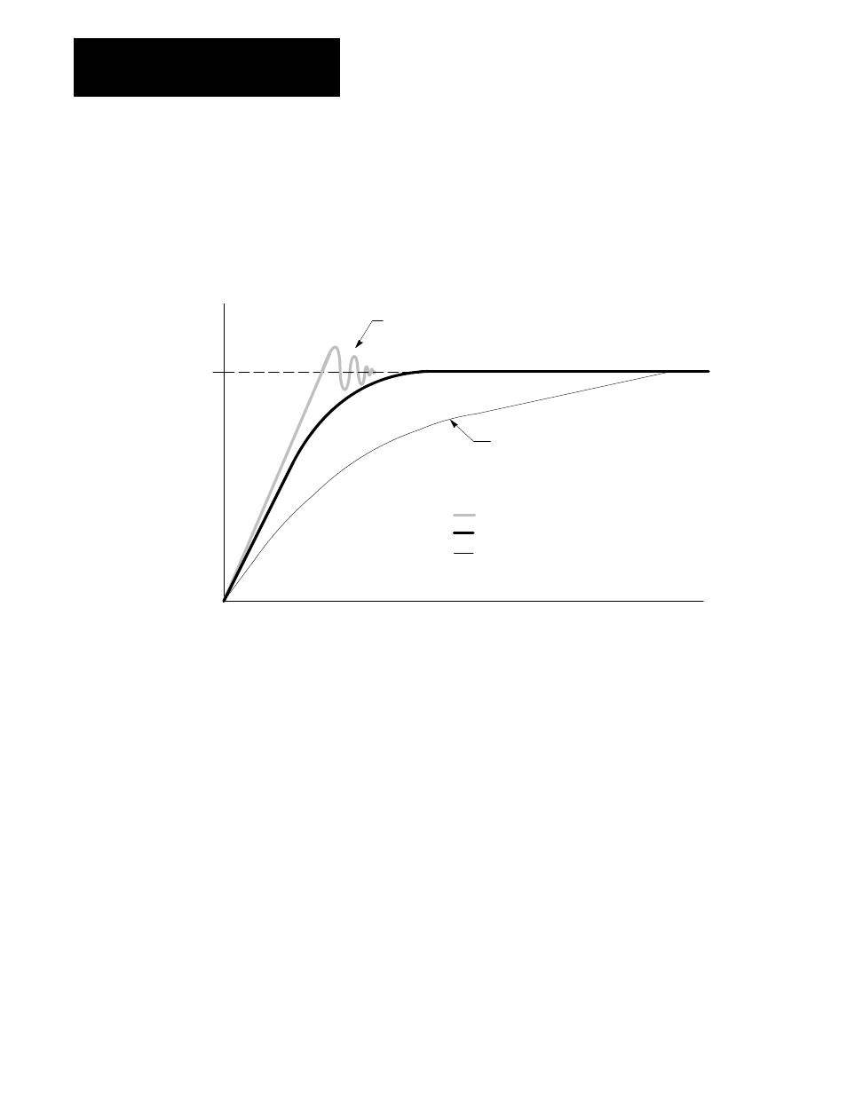
Figure A.1
Acceleration Curve for Tuning
Time
Velocity
Commanded Velocity
Underdampened (Velocity Proportional Gain too High)
Optimal Acceleration Curve
Overdampened (Velocity Proportional Gain too Low)
Underdampened Causes Overshoot of Commanded Velocity
Overdampened Causes Sluggish Response
With the Velocity Proportional Gain set as discussed in Table A.A, most
systems will be overdampened as shown in Figure A.1.
Important: If your system strip chart record is either off the scale or too
small to easily read, you can scale the output to the recorder using patch
AMP parameters 910, 920, or 930 (see page A-6 for a description). By
raising the value of this parameter you will scale down the velocity output.
By lowering the value of this parameter you will scale up the velocity
output. Remember these are the spindle gear range scale factors. Be sure
to restore them before reconnecting your spindle.
2.
Adjust the velocity proportional gain (see page 40-13) and change the
velocity proportional gain for the axis you are tuning. If the
acceleration curve appears overdampened, raise the value of the
velocity proportional gain. If the acceleration curve appears
underdampened lower the velocity proportional gain.
3.
Re-run your tuning part program. Continue adjusting the velocity
proportional gain until the axis just becomes underdampened (small
sharp velocity overshoot occurs over the command velocity).