Gpio port – Grass Valley Maestro Master Control Installation v.2.4.0 User Manual
Page 96
96
MAESTRO Installation and Service Manual
Section 2 — Installation Planning
Positronic Industries
Connector housing description - CONN F/M Cable 44PIN DSUB; part
number - DD44M00GEX/AA
Connector pins description - CONN O/M PIN 22-30AWG CRIMP; part
number - MC8022D/AA
GPIO Port
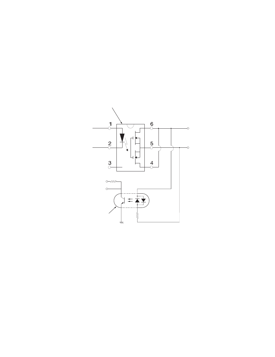
Figure 43. GPIO Port Circuitry. For Pinouts see
.
V
CC
From
Maestro
logic
GPIO
rear panel
connector
To
Maestro
logic
V
OUT
ON = 3-10 V, 4.25 mA max.
Input photocoupler
NEC PS2705-1
Maximum current through relay = 250 mA
Maximum voltage for relay = 24 V
Output relay
International Rectifier PVG613
2.2 K, 0.1 W
B
A
10K
Note: Use pins "A" and "B" only when
connecting Maestro to an external device
Do not connect a third conductor as a
common ground path (e.g., do not
connect the connector shields).
- Concerto Routing Matrix v.1.7.6.1 Concerto Routing Matrix v.1.8.1 Concerto Routing Matrix v.1.7.5 Kayenne Installation v.4.0 Kayenne Installation v.3.0 Kayenne K-Frame Installation v.6.0 Kayenne K-Frame Installation v.7.0 Kayenne K-Frame Installation v.8.0 Karrera K-Frame S-Series Installation v.8.0 Karrera Video Production Center Installation v.6.0 Karrera Video Production Center Installation v.7.0 Karrera Video Production Center Installation v.4.1 Karrera Video Production Center Installation v.4.0 7600REF v5.0 7600REF v3.0.0.8 7600REF v5.0 Installation 7600REF v3.0.0.8 Installation 7620PX-5 Installation 2012 7620PX Installation 2012 KayenneKayenne v.2.0 v.2.0 Maestro Master Control Installation v.2.3.0 Maestro Master Control Installation v.2.0.0 Maestro Master Control v.2.3.0 7620PX 2012 7620PX-5 2012 7620PX 2008 MVMC 3G VMCR 3G 8900F GeckoFlex Frames Concerto Compact Routing System GPIO-4848 Jupiter Maestro Master Control v.2.2.0 Maestro Master Control v.2.0.0 Maestro Master Control v.2.4.0 Maestro Master Control Installation v.2.2.0 Maestro Master Control Installation v.1.5.1 Maestro Master Control Installation v.1.7