Grass Valley Maestro Master Control Installation v.2.4.0 User Manual
Page 198
198
MAESTRO Installation and Service Manual
Section 5 — The Maestro Configuration Editor
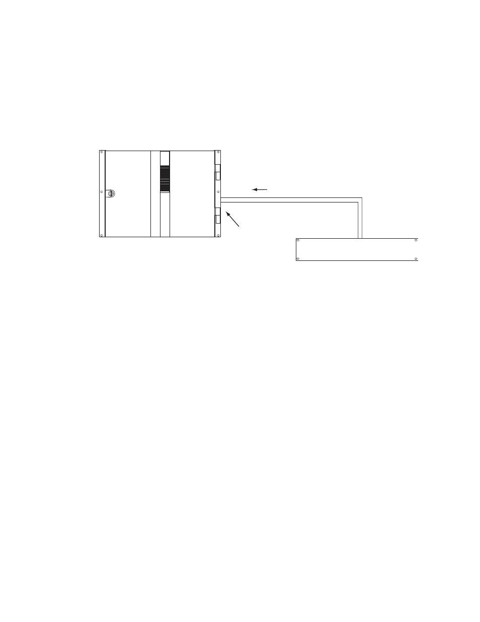
Maestro Controlled By or Controlling an External Device
The GPIO connector on the Maestro rear panel can be used to receive an
“Action: Transition” signal from a controlling external device (
or to transmit an “Action: Transition in Progress” signal to a controlled
external device (
).
Figure 106. GPI Connections to External Controlling Device
When used to control an external device, Maestro systems require installa-
tion of a leakage-current swamping resistor in the GPO circuit. This resistor
is used to prevent leakage current from reaching the external device when
the Maestro photo-coupler relay is open. The resistor is always placed
across the input relay of the external device.
show examples of connections to controlled
external devices containing a small mechanical or solid-state relay, along
with a suggested location and value for the swamping resistor. A supply
voltage greater than +5 V can be used (up to + 10 V), but in that case the
power rating of the resistor would need to be increased accordingly.
TTL
Trigger
Port
Maestro
GPI Port/Photo-coupler
See Notes
1A
1B
Note 1
Connections between Maestro
GPIO Connector and controlling
external device are bipolar.
Note 2
Maximum current through Maestro photo-coupler = 4.25 mA
"High" range for photo-coupler = 3-10 V
"Transition" signal
Controlling external device
- Concerto Routing Matrix v.1.7.6.1 Concerto Routing Matrix v.1.8.1 Concerto Routing Matrix v.1.7.5 Kayenne Installation v.4.0 Kayenne Installation v.3.0 Kayenne K-Frame Installation v.6.0 Kayenne K-Frame Installation v.7.0 Kayenne K-Frame Installation v.8.0 Karrera K-Frame S-Series Installation v.8.0 Karrera Video Production Center Installation v.6.0 Karrera Video Production Center Installation v.7.0 Karrera Video Production Center Installation v.4.1 Karrera Video Production Center Installation v.4.0 7600REF v5.0 7600REF v3.0.0.8 7600REF v5.0 Installation 7600REF v3.0.0.8 Installation 7620PX-5 Installation 2012 7620PX Installation 2012 KayenneKayenne v.2.0 v.2.0 Maestro Master Control Installation v.2.3.0 Maestro Master Control Installation v.2.0.0 Maestro Master Control v.2.3.0 7620PX 2012 7620PX-5 2012 7620PX 2008 MVMC 3G VMCR 3G 8900F GeckoFlex Frames Concerto Compact Routing System GPIO-4848 Jupiter Maestro Master Control v.2.2.0 Maestro Master Control v.2.0.0 Maestro Master Control v.2.4.0 Maestro Master Control Installation v.2.2.0 Maestro Master Control Installation v.1.5.1 Maestro Master Control Installation v.1.7