E shown in, Figure 267 – Grass Valley Maestro Master Control Installation v.2.4.0 User Manual
Page 372

372
MAESTRO — Installation and Service Manual
Section 12 — Dual-Channel DVE Hardware Installation
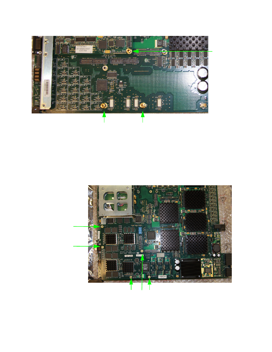
Figure 267. DVE Stand-off Locations
2.
Place the DVE board over the Main board and align the connectors and
screw holes on the DVE board with the connectors and stand-offs on the
Maestro Main board.
3.
Fasten the DVE board in place on the Maestro Main board using the
mounting screws.
Figure 268. DVE Board Installed on the Maestro Main Board
illustrates a DVE board installed.
Large Stand-off Connections
Small Stand-off
Connection
Mounting Screw locations
Mounting Screw
locations
This manual is related to the following products:
- Concerto Routing Matrix v.1.7.6.1 Concerto Routing Matrix v.1.8.1 Concerto Routing Matrix v.1.7.5 Kayenne Installation v.4.0 Kayenne Installation v.3.0 Kayenne K-Frame Installation v.6.0 Kayenne K-Frame Installation v.7.0 Kayenne K-Frame Installation v.8.0 Karrera K-Frame S-Series Installation v.8.0 Karrera Video Production Center Installation v.6.0 Karrera Video Production Center Installation v.7.0 Karrera Video Production Center Installation v.4.1 Karrera Video Production Center Installation v.4.0 7600REF v5.0 7600REF v3.0.0.8 7600REF v5.0 Installation 7600REF v3.0.0.8 Installation 7620PX-5 Installation 2012 7620PX Installation 2012 KayenneKayenne v.2.0 v.2.0 Maestro Master Control Installation v.2.3.0 Maestro Master Control Installation v.2.0.0 Maestro Master Control v.2.3.0 7620PX 2012 7620PX-5 2012 7620PX 2008 MVMC 3G VMCR 3G 8900F GeckoFlex Frames Concerto Compact Routing System GPIO-4848 Jupiter Maestro Master Control v.2.2.0 Maestro Master Control v.2.0.0 Maestro Master Control v.2.4.0 Maestro Master Control Installation v.2.2.0 Maestro Master Control Installation v.1.5.1 Maestro Master Control Installation v.1.7
