Control cables, Pin control connectors, Pin control connec- tors – Grass Valley Maestro Master Control Installation v.2.4.0 User Manual
Page 95
MAESTRO Installation and Service Manual
95
Control Cables
Control Cables
Most control cables must be built locally. Exceptions include the CAT5
network cables, which are available from third-party suppliers, and certain
RS-422 serial control cables, which can be purchased from Grass Valley.
44-pin Control Connectors
Pinouts for 44-pin control connectors are shown in
. For Dolby E
Metadata wiring diagrams, see
. The GPIO pins can be used for con-
nection to a Jupiter/MI-3040 tally system; for more information, refer to
. For a diagram of the GPIO port circuitry, see
.
Note
Pins 43 and 44 of the “GPIO” connector are reserved for linear time code
connection.
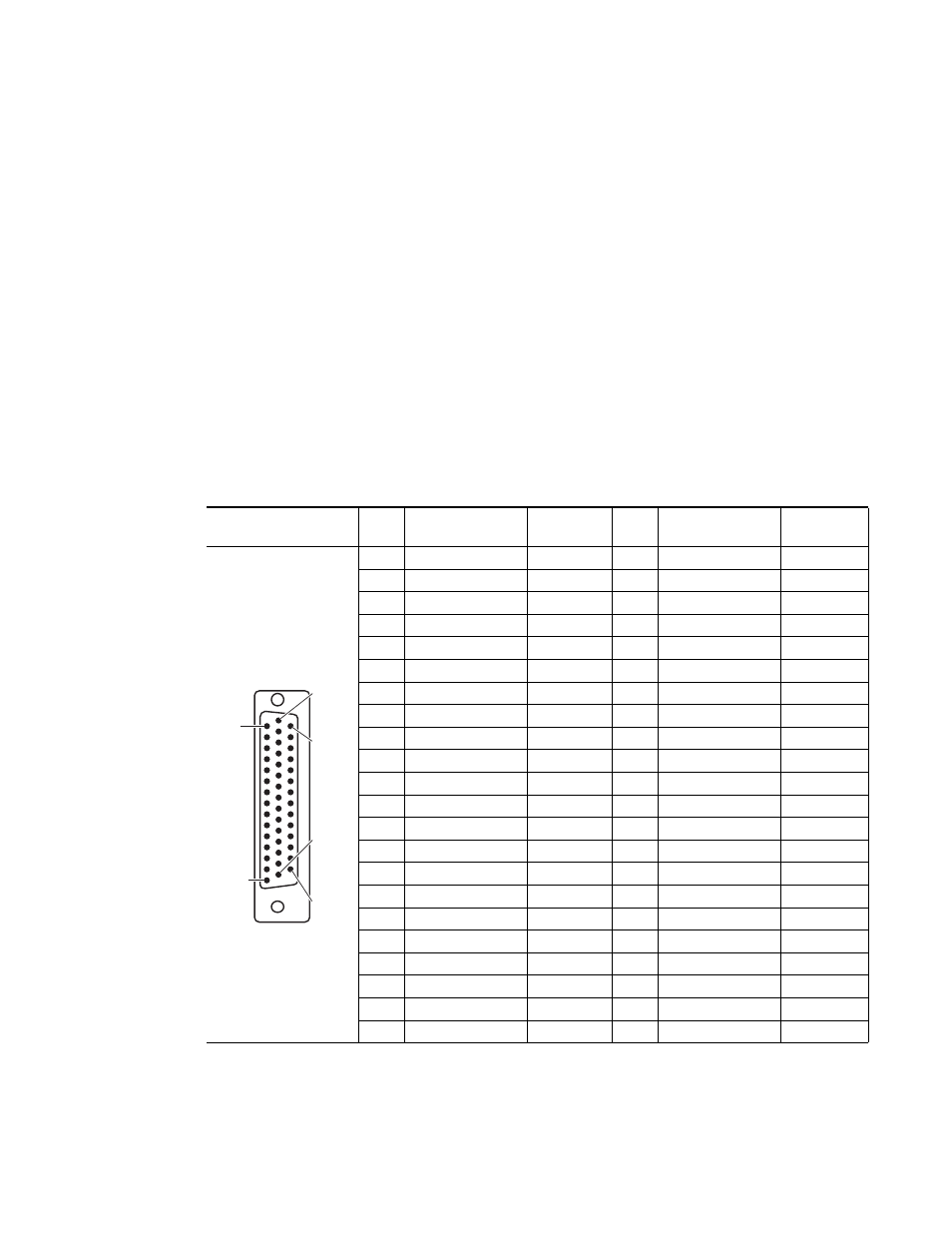
Table 9. Maestro Rear Panel, 44-pin Connector Pinouts
Although other suppliers may be available, the 44-pin connector housing
and pins may be obtained from:
Shielded 44-Pin D;
socket contacts
Pin
Metadata
GPIO
Pin
Metadata
GPIO
1
Program TX+
1A
23
10A
2
Program TX-
1B
24
10B
3
Background A RX+
2A
25
GND
4
Background A RX-
2B
26
NC
11A
5
PGM/BGA FG/SHIELD
GND
27
NC
11B
6
Preset TX+
3A
28
12A
7
Preset TX-
3B
29
12B
8
Background B RX+
4A
30
GND
9
Background B RX-
4B
31
NC
13A
10
PST/BGB FG/SHIELD
GND
32
NC
13B
11
Clean Feed 1 TX+
5A
33
14A
12
Clean Feed 1 TX-
5B
34
14B
13
Background C RX+
6A
35
GND
14
Background C RX-
6B
36
NC
15A
15
CF1/BGC FG/SHIELD
GND
37
NC
15B
16
Pre Listen TX+
7A
38
16A
17
Pre Listen TX-
7B
39
Over D RX-
16B
18
Background D RX+
8A
40
GND
19
Background D RX-
8B
41
NC
NC
20
PRL/BGD FG/SHIELD
GND
42
NC
NC
21
Monitor TX+
9A
43
NC
LTC RX IN+
22
Monitor TX-
9B
44
NC
LTC RX IN–
D-44 Female
Pin 1
Pin 15
Pin 30
Pin 44
Pin 16
Pin 31
- Concerto Routing Matrix v.1.7.6.1 Concerto Routing Matrix v.1.8.1 Concerto Routing Matrix v.1.7.5 Kayenne Installation v.4.0 Kayenne Installation v.3.0 Kayenne K-Frame Installation v.6.0 Kayenne K-Frame Installation v.7.0 Kayenne K-Frame Installation v.8.0 Karrera K-Frame S-Series Installation v.8.0 Karrera Video Production Center Installation v.6.0 Karrera Video Production Center Installation v.7.0 Karrera Video Production Center Installation v.4.1 Karrera Video Production Center Installation v.4.0 7600REF v5.0 7600REF v3.0.0.8 7600REF v5.0 Installation 7600REF v3.0.0.8 Installation 7620PX-5 Installation 2012 7620PX Installation 2012 KayenneKayenne v.2.0 v.2.0 Maestro Master Control Installation v.2.3.0 Maestro Master Control Installation v.2.0.0 Maestro Master Control v.2.3.0 7620PX 2012 7620PX-5 2012 7620PX 2008 MVMC 3G VMCR 3G 8900F GeckoFlex Frames Concerto Compact Routing System GPIO-4848 Jupiter Maestro Master Control v.2.2.0 Maestro Master Control v.2.0.0 Maestro Master Control v.2.4.0 Maestro Master Control Installation v.2.2.0 Maestro Master Control Installation v.1.5.1 Maestro Master Control Installation v.1.7