Figure 23 on, Bus tally mode (jupiter systems with mi-3040) – Grass Valley Maestro Master Control Installation v.2.4.0 User Manual
Page 72
72
MAESTRO Installation and Service Manual
Section 2 — Installation Planning
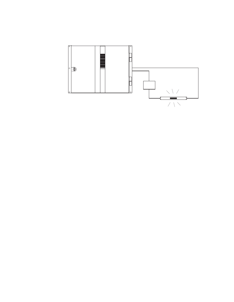
Figure 23. Example of Wiring for Single Port Connection between Maestro and Tally Light
For pinouts of the GPIO connector, see
. For a diagram of
the GPIO port circuitry, see
.
Bus Tally Mode (Jupiter Systems with MI-3040)
The GPIO connector on the Maestro rear panel can be configured to
provide an indication as to which Maestro input bus has been selected for
the Program (Air) output. The GPIO connector can be connected to a
Jupiter Control System MI-3040 General Purpose/Tally Interface. The
Jupiter Control System can be configured to determine which router input
(source) is currently switched to the Maestro input bus that is on Air;
Jupiter can then activate the appropriate MI-3040 relay connector in order
to illuminate a tally light. See
and
.
Maestro
GPIO Connector
pins for Port 1
See Notes
Note 1
Connections between Maestro GPIO Connector
and current source connectors are bipolar;
e.g., GPIO "A" can be connected to either plus
or minus source.
Note 2
Maximum current through Maestro GPIO relay = 250 mA.
Maximum voltage = 24 V.
A
B
Current
source
Tally light
- Concerto Routing Matrix v.1.7.6.1 Concerto Routing Matrix v.1.8.1 Concerto Routing Matrix v.1.7.5 Kayenne Installation v.4.0 Kayenne Installation v.3.0 Kayenne K-Frame Installation v.6.0 Kayenne K-Frame Installation v.7.0 Kayenne K-Frame Installation v.8.0 Karrera K-Frame S-Series Installation v.8.0 Karrera Video Production Center Installation v.6.0 Karrera Video Production Center Installation v.7.0 Karrera Video Production Center Installation v.4.1 Karrera Video Production Center Installation v.4.0 7600REF v5.0 7600REF v3.0.0.8 7600REF v5.0 Installation 7600REF v3.0.0.8 Installation 7620PX-5 Installation 2012 7620PX Installation 2012 KayenneKayenne v.2.0 v.2.0 Maestro Master Control Installation v.2.3.0 Maestro Master Control Installation v.2.0.0 Maestro Master Control v.2.3.0 7620PX 2012 7620PX-5 2012 7620PX 2008 MVMC 3G VMCR 3G 8900F GeckoFlex Frames Concerto Compact Routing System GPIO-4848 Jupiter Maestro Master Control v.2.2.0 Maestro Master Control v.2.0.0 Maestro Master Control v.2.4.0 Maestro Master Control Installation v.2.2.0 Maestro Master Control Installation v.1.5.1 Maestro Master Control Installation v.1.7