General architecture, Configuration parameters, General architecture -4 – Altera Embedded Peripherals IP User Manual
Page 90: Configuration parameters -4, Table 9-7: dma sideband signals, Input tx dma acknowledge, Input rx dma acknowledge, Output tx dma request, Output rx dma request, Output tx dma single request
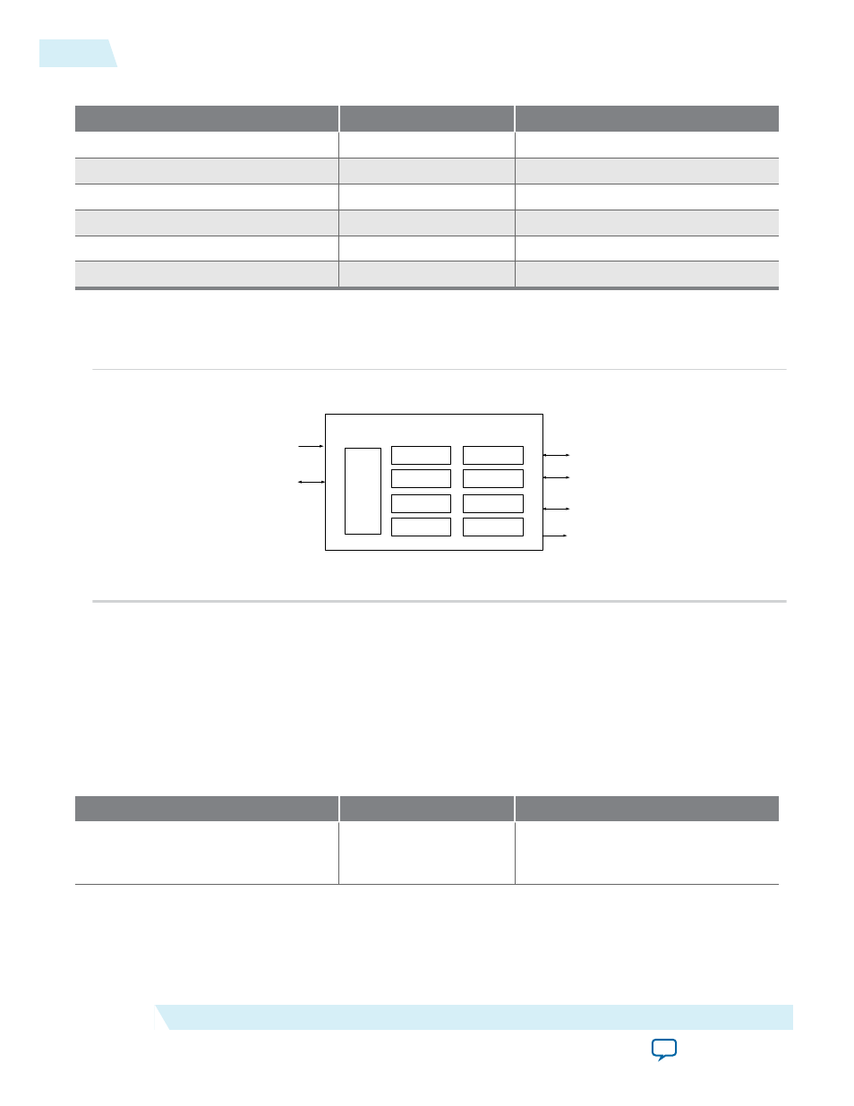
Table 9-7: DMA Sideband Signals
Pin Name
Direction
Description
dma_tx_ack_n
Input
TX DMA acknowledge
dma_rx_ack_n
Input
RX DMA acknowledge
dma_tx_req_n
Output
TX DMA request
dma_rx_req_n
Output
RX DMA request
dma_tx_single_n
Output
TX DMA single request
dma_rx_single_n
Output
RX DMA single request
General Architecture
Figure 9-1: Soft-UART High Level Architecture
TX Shifter
RX Shifter
TX Fifo
RX Fifo
CSR
Interface
DMA Controller
Clock Generator
TX Flow Control
RX Flow Control
16550 UART Core
Avalon MM
Slave Interface
Clock & Reset
RS -232 Serial
Interface
RS -232 Modem
Interface
DMA Handshaking
Interface
IRQ
The figure above shows the high level architecture of the UART IP. Both Transmit and Receive logic have
their own dedicated control & data path. An interrupt block and clock generator block is also present to
service both transmit and receive logic.
Configuration Parameters
The table below shows all the parameters that can be used to configure the UART. (
_hw.tcl
) is the
mechanism used to enforce and validate correct parameter settings.
Table 9-8: Configuration Parameters
Parameter Name
Description
Default
FIFO_MODE
1 = FIFO Mode Enabled
0 = FIFO Mode Disabled
1
9-4
General Architecture
UG-01085
2014.24.07
Altera Corporation
16550 UART