Altera Embedded Peripherals IP User Manual
Page 254
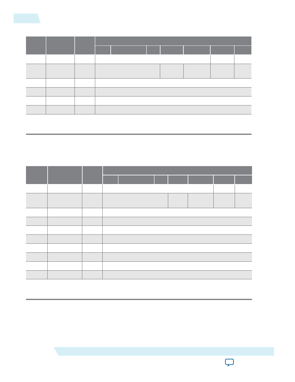
Table 25-3: Register Map—32-bit Timer
Offset
Name
R/W
Description of Bits
15
...
4
3
2
1
0
0
status
RW
RUN
TO
1
control
RW
STOP
START
CONT
IT
O
2
periodl
RW
Timeout Period – 1 (bits [15:0])
3
periodh
RW
Timeout Period – 1 (bits [31:16])
4
snapl
RW
Counter Snapshot (bits [15:0])
5
snaph
RW
Counter Snapshot (bits [31:16])
1. Reserved. Read values are undefined. Write zero.
.
Table 25-4: Register Map—64-bit Timer
Offset
Name
R/W
Description of Bits
15
...
4
3
2
1
0
0
status
RW
RUN
TO
1
control
RW
STOP
START
CONT
IT
O
2
period_0
RW
Timeout Period – 1 (bits [15:0])
3
period_1
RW
Timeout Period – 1 (bits [31:16])
4
period_2
RW
Timeout Period – 1 (bits [47:32])
5
period_3
RW
Timeout Period – 1 (bits [63:48])
6
snap_0
RW
Counter Snapshot (bits [15:0])
7
snap_1
RW
Counter Snapshot (bits [31:16])
8
snap_2
RW
Counter Snapshot (bits [47:32])
9
snap_3
RW
Counter Snapshot (bits [63:48])
1. Reserved. Read values are undefined. Write zero.
status Register
The
status
register has two defined bits.
25-6
Register Map
UG-01085
2014.24.07
Altera Corporation
Interval Timer Core
- MAX 10 JTAG (15 pages)
- MAX 10 Power (21 pages)
- Unique Chip ID (12 pages)
- Remote Update IP Core (43 pages)
- Device-Specific Power Delivery Network (28 pages)
- Device-Specific Power Delivery Network (32 pages)
- Hybrid Memory Cube Controller (69 pages)
- ALTDQ_DQS IP (117 pages)
- MAX 10 Embedded Memory (71 pages)
- MAX 10 Embedded Multipliers (37 pages)
- MAX 10 Clocking and PLL (86 pages)
- MAX 10 FPGA (26 pages)
- MAX 10 FPGA (56 pages)
- USB-Blaster II (22 pages)
- GPIO (22 pages)
- LVDS SERDES (27 pages)
- User Flash Memory (33 pages)
- ALTDQ_DQS2 (100 pages)
- Avalon Tri-State Conduit Components (18 pages)
- Cyclone V Avalon-MM (166 pages)
- Cyclone III FPGA Starter Kit (36 pages)
- Cyclone V Avalon-ST (248 pages)
- Stratix V Avalon-ST (286 pages)
- Stratix V Avalon-ST (293 pages)
- DDR3 SDRAM High-Performance Controller and ALTMEMPHY IP (10 pages)
- Arria 10 Avalon-ST (275 pages)
- Avalon Verification IP Suite (224 pages)
- Avalon Verification IP Suite (178 pages)
- FFT MegaCore Function (50 pages)
- DDR2 SDRAM High-Performance Controllers and ALTMEMPHY IP (140 pages)
- Floating-Point (157 pages)
- Integer Arithmetic IP (157 pages)
- JESD204B IP (158 pages)
- Low Latency Ethernet 10G MAC (109 pages)
- LVDS SERDES Transmitter / Receiver (72 pages)
- Nios II Embedded Evaluation Kit Cyclone III Edition (3 pages)
- Nios II Embedded Evaluation Kit Cyclone III Edition (80 pages)
- IP Compiler for PCI Express (372 pages)
- Parallel Flash Loader IP (57 pages)
- Nios II C2H Compiler (138 pages)
- RAM-Based Shift Register (26 pages)
- RAM Initializer (36 pages)
- Phase-Locked Loop Reconfiguration IP Core (51 pages)
- DCFIFO (28 pages)