Control register, Frequency register – Altera Embedded Peripherals IP User Manual
Page 331
instance to have only five counters, then only addressess 0x0 to 0x4 return a valid value when you try to
read from it. When the IP user tries to read from an invalid address, the IP returns binary ‘0’ value.”.
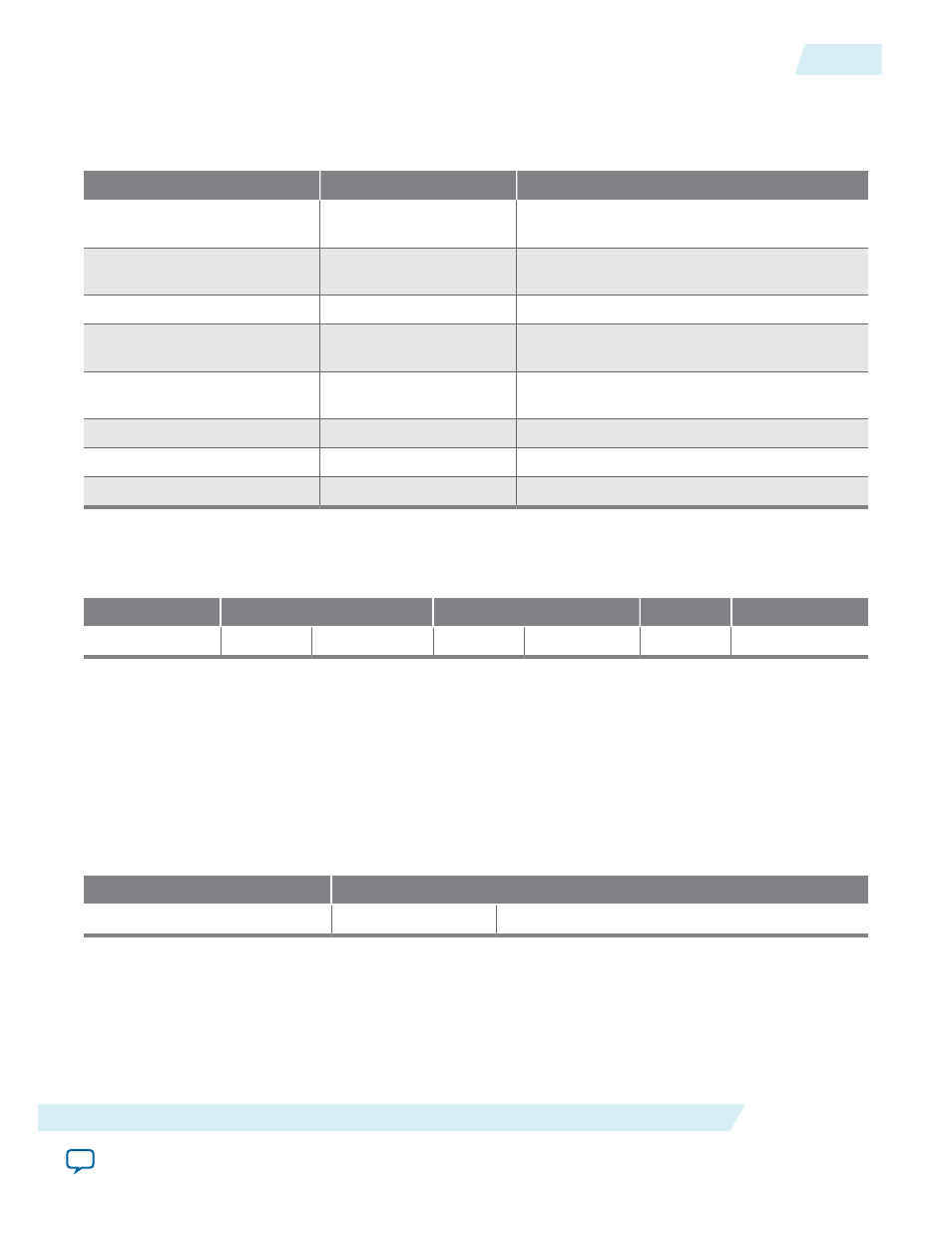
Table 34-1: ILC Register Mapping
Word Address Offset
Register/ Queue Name
Attribute
0x0
IRQ_0 Latency Data
Registers
Read access only
0x1
IRQ_1 Latency Data
Registers
Read access only
...
...
...
0x1F
IRQ_31 Latency Data
Registers
Read access only
0x20
Control Registers
Read and Write access on LSB and Read only for
the remaining bits
0x21
Frequency Registers
Read access only
0x22
Counter Stop Registers
Read and Write access
0x23
Read data Valid Registers
Read access only
Control Register
Table 34-2: ILC Control Register Fields
Field Name
ILC Version
IRQ Port Count
IRQ TYPE
Global Enable
Bit Location
31
8 7
2
1
0
The control registers of the Interrupt Latency Counter is divided into four fields. The LSB is the global
enable bit which by default stores a binary ‘0’. To enable the IP to work, it must be set to binary ‘1’. The
next bit denotes the IRQ type the IP is configured to measure, with binary ‘0’ indicating it is sensitive to
level type IRQ signal; while binary ‘1’ means the IP is accepting pulse type interrupt signal. The next six
bits stores the number of IRQ port count configured through the Qsys GUI. Bit 8 through bit 31 stores the
revision value of the ILC instance.
Frequency Register
Table 34-3: Frequency Register
Field Name
System Frequency
Bit Location
31
0
The frequency registers stores the clock frequency supplied to the IP. This 32-bit read only register holds
system frequency data in Hz. For example, a 50 MHz clock signal is represented by hexadecimal
0x2FAF080.
UG-01085
2014.24.07
Control Register
34-3
Altera Interrupt Latency Counter
Altera Corporation