Pixel converter, Functional description, Parameters – Altera Embedded Peripherals IP User Manual
Page 246: Signals, Pixel converter -5, Functional description -5, Parameters -5, Signals -5, Global signals
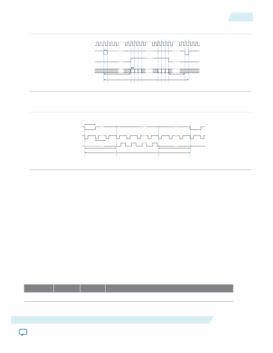
Figure 24-4: Horizontal Synchronization Timing—24 Bits DataWidth and 1 Beat Per Pixel
clk
hd
den
rgb_out
RGB
Horizontal synchronization pulse
Horizontal blank pixels
Horizontal front porch
1 pixel
RGBRGB
RGBRGBRGB
Horizontal synchronization width
Figure 24-5: Vertical Synchronization Timing—8 Bits DataWidth and 3 Beats Per Pixel / 24 Bits
DataWidth and 1 Beat Per Pixel
hd
den
Vertical blank lines
Horizontal synchronization width
vd
Vertical synchronization width
Vertical front porch
Vertical synchronization pulse
Pixel Converter
This section describes the hardware structure and functionality of the pixel converter core.
Functional Description
The pixel converter core receives pixel data on its Avalon-ST input interface and transforms the pixel data
to the format required by the video sync generator. The least significant byte of the 32-bit wide pixel data
is removed and the remaining 24 bits are wired directly to the core's Avalon-ST output interface.
Parameters
You can configure the following parameter:
• Source symbols per beat—The number of symbols per beat on the Avalon-ST source interface.
Signals
Table 24-3: Pixel Converter Input Interface Signals
Signal Name Width (Bits)
Direction
Description
Global Signals
UG-01085
2014.24.07
Pixel Converter
24-5
Video Sync Generator and Pixel Converter Cores
Altera Corporation