Dma descriptors, Dma descriptors -6, Bit set to 0 because the core relies on a cleared – Altera Embedded Peripherals IP User Manual
Page 197: Register and initiates the transfer by setting the, Bit in the, Bit, the core sets the
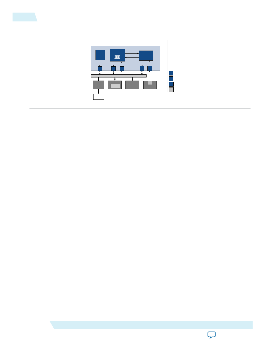
Figure 21-5: Example of Stream-to-Memory Configuration
S RC
S RC
M
Ava lon-MM Ma s ter P ort
S
Avalon-MM S la ve P ort
Ava lon -S T So urce Port
Ava lon-S T S ink P ort
SO P C Builde r Syst em
Alte ra FPG A
S ca tte r Ga the r DMA Con trolle r Core
Rd
S
M
Wr
M
M
c omma nd
st atus
SN K
Con trol
&
Sta tus
Re gi s ters
Nios II
Pro c e s s o r
DDR2
S DRAM
Memo ry
Con trolle r
Sy s te m Inte rconne ct Fa bric
Memo ry
De s criptor
Ta ble
De s c riptor
Proc e s s or
Block
S NK
DMA Write Blo c k
S tre aming
Co mpon e nt
SR C
DMA Descriptors
DMA descriptors specify data transfers to be performed. The SG-DMA core uses a dedicated interface to
read and write the descriptors. These descriptors, which are stored as a linked list, can be stored on an on-
chip or off-chip memory and can be arbitrarily long.
Storing the descriptor list in an external memory frees up resources in the FPGA; however, an external
descriptor list increases the overhead involved when the descriptor processor reads and updates the list.
The SG-DMA core has an internal FIFO to store descriptors read from memory, which allows the core to
perform descriptor read, execute, and write back operations in parallel, hiding the descriptor access and
processing overhead.
The descriptors must be initialized and aligned on a 32-bit boundary. The last descriptor in the list must
have its
OWNED_BY_HW
bit set to 0 because the core relies on a cleared
OWNED_BY_HW
bit to stop processing.
See the DMA Descriptors section for the structure of the DMA descriptor.
Descriptor Processing
The following steps describe how the DMA descriptors are processed:
1. Software builds the descriptor linked list. See the Building and Updating Descriptors List section for
more information on how to build and update the descriptor linked list.
2. Software writes the address of the first descriptor to the
next_descriptor_pointer
register and
initiates the transfer by setting the
RUN
bit in the
control
register to 1. See the Software Programming
Model section for more information on the registers.
On the next clock cycle following the assertion of the
RUN
bit, the core sets the
BUSY
bit in the
status
register to 1 to indicate that descriptor processing is executing.
3. The descriptor processor block reads the address of the first descriptor from the
next_descriptor_pointer
register and pushes the retrieved descriptor into the command FIFO,
which feeds commands to both the DMA read and write blocks. As soon as the first descriptor is read,
the block reads the next descriptor and pushes it into the command FIFO. One descriptor is always
read in advance thus maximizing throughput.
4. The core performs the data transfer.
21-6
DMA Descriptors
UG-01085
2014.24.07
Altera Corporation
Scatter-Gather DMA Controller Core