Altera Embedded Peripherals IP User Manual
Page 271
• One optional Avalon-ST interface input interface to receive the Avalon-ST output in systems with
daisy-chained VICs
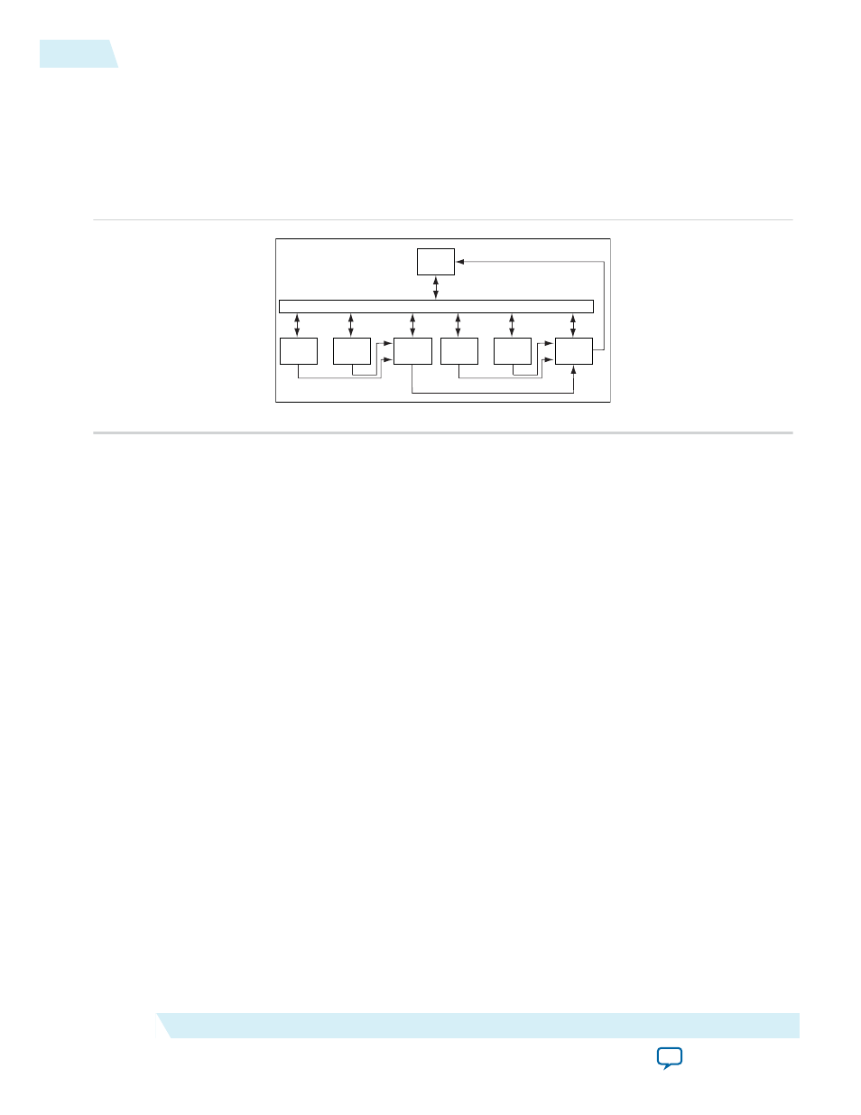
The Sample System Layout Figure below outlines the basic layout of a system containing two VIC
components.
Figure 28-1: Sample System Layout
The VIC core provides the following features:
Avalon-MM Interconnect Fa bric
VIC
CPU
IRQ
Core
Avalon-ST
...
...
IRQ
VIC
IRQ
Core
...
...
IRQ
Avalon-ST
Cor
o
C
e
re
To use the VIC, the processor in your system needs to have a matching Avalon-ST interface to accept
the interrupt information, such as the Nios
®
II processor's external interrupt controller interface.
The characteristics of each interrupt port are configured via the Avalon-MM slave interface. When you
need more than 32 interrupt ports, you can daisy chain multiple VICs together.
• Separate programmable requested interrupt level (RIL) for each interrupt
• Separate programmable requested register set (RRS) for each interrupt, to tell the interrupt handler
which processor register set to use
• Separate programmable requested non-maskable interrupt (RNMI) flag for each interrupt, to control
whether each interrupt is maskable or non-maskable
• Software-controlled priority arbitration scheme
The VIC core is SOPC Builder-ready and integrates easily into any SOPC Builder-generated system.
For the Nios II processor, Altera provides Hardware Abstraction Layer (HAL) driver routines for the
VIC core. Refer to Altera HAL Software Programming Model section for HAL support details.
28-2
Core Overview
UG-01085
2014.24.07
Altera Corporation
Vectored Interrupt Controller Core