Functional description, Configuration, Preset settings – Altera Embedded Peripherals IP User Manual
Page 48: Functional description -2, Configuration -2, Attributes page
Functional Description
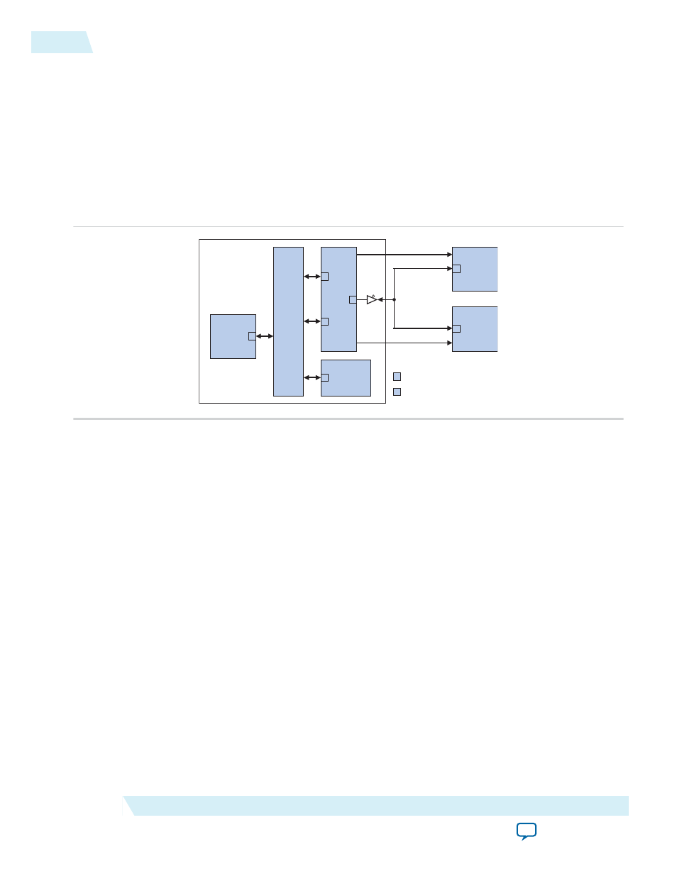
The figure below shows a block diagram of the CFI controller in a typical system configuration. The
Avalon Memory-Mapped (Avalon-MM) interface for flash devices is connected through an Avalon-MM
tristate bridge. The tristate bridge creates an off-chip memory bus that allows the flash chip to share
address and data pins with other memory chips. It provides separate chipselect, read, and write pins to
each chip connected to the memory bus. The CFI controller hardware is minimal; it is simply an Avalon-
MM tristate slave port configured with waitstates, setup, and hold time appropriate for the target flash
chip. This slave port is capable of Avalon-MM tristate slave read and write transfers.
Figure 5-1: System Integrating a CFI Controller
System Interconnect
Fab
ric
S Avalon-MM Slave Port
M Avalon-MM Master
Port
A
valon-MM
T
ristate Brid
g
e
S
S
M
M
Avalon-MM
Master
(e.g. CPU)
S
On-Chip
Slave
Peripheral
Altera FPGA
S
Flash
Memory
Chip
S
Other
Memory
chipselect,
read_n, write_n
chipselect,
read_n, write_n
flash
other
Avalon-MM master ports can perform read transfers directly from the CFI controller's Avalon-MM port.
See the Software Programming Model section for more detail on writing/erasing flash memory.
Configuration
The following sections describe the available configuration options.
Attributes Page
The options on this page control the basic hardware configuration of the CFI controller.
Preset Settings
The Presets setting is a drop-down menu of flash chips that have already been characterized for use with
the CFI controller. After you select one of the chips in the Presets menu, the wizard updates all settings on
both tabs (except for the Board Info setting) to work with the specified flash chip.
5-2
Functional Description
UG-01085
2014.24.07
Altera Corporation
Common Flash Interface Controller Core