Hardware simulation considerations, Register definitions and bit list, Status register – Altera Embedded Peripherals IP User Manual
Page 316: Hardware simulation considerations -5, Register definitions and bit list -5, Status register -5
Hardware Simulation Considerations
The HDL files generated by SOPC Builder for the PLL cores are suitable for both synthesis and
simulation. The PLL cores support the standard SOPC Builder simulation flow, so there are no special
considerations for hardware simulation.
Register Definitions and Bit List
Device drivers can control and communicate with the cores through two memory-mapped registers,
status
and
control
. The width of these registers are 32 bits in the Avalon ALTPLL core but only 16 bits
in the PLL core.
In the PLL core, the
status
and
control
bits shown in the PLL Cores Register map below are present
only if they have been created in the ALTPLL MegaWizard Plug-In Manager, and set to Register on the
Interface page in the PLL wizard. These registers are always created in the Avalon ALTPLL core.
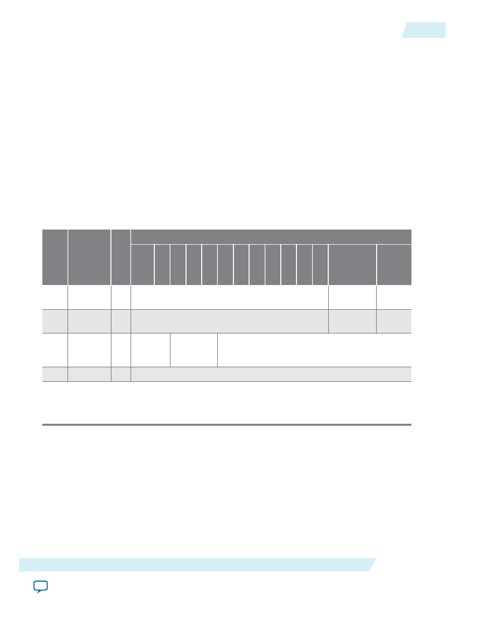
Table 32-2: PLL Cores Register Map
Offse
t
Register
Name
R/W
Bit Description
31/
15
30 29 ...
9
8
7
6
5
4
3
2
1
0
0
status
R/O
phasedone
lock
ed
1
control
R/
W
pfdena
ares
et
2 phase
reconfig
control
R/
W
phase
counter_number
3 —
—
Undefined
1. Reserved. Read values are undefined. When writing, set reserved bits to zero.
2. The registers are 32-bit wide in the Avalon ALTPLL core and 16-bit wide in the PLL core.
Status Register
Embedded software can access the PLL status via the
status
register. Writing to
status
has no effect.
UG-01085
2014.24.07
Hardware Simulation Considerations
32-5
PLL Cores
Altera Corporation