Status interface, Clocking modes, Configuration – Altera Embedded Peripherals IP User Manual
Page 160: Status interface -5, Clocking modes -5, Configuration -5

is exactly the same as for the Avalon-MM to Avalon-ST FIFO core. See the for Memory Map table for
more information.
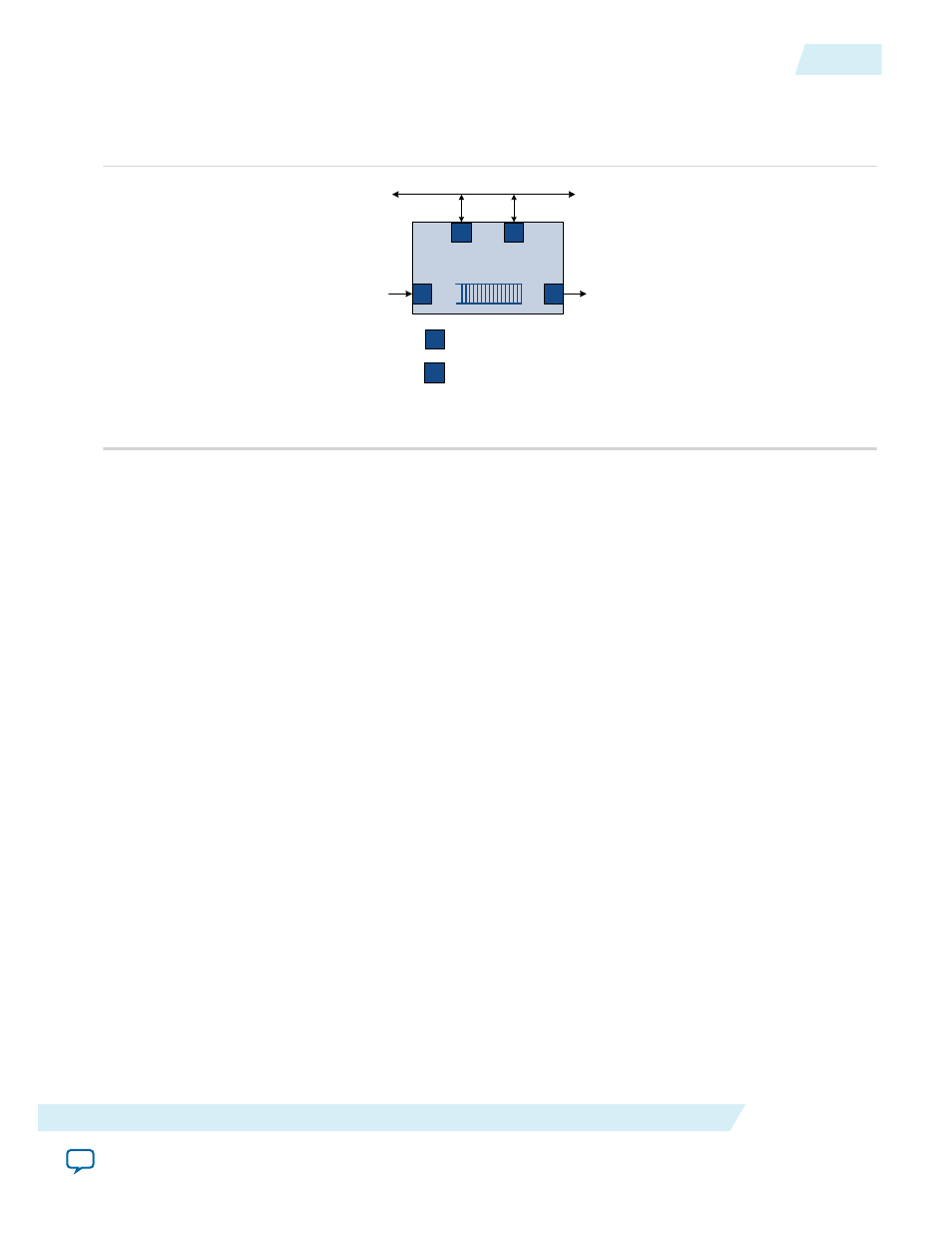
Figure 16-4: FIFO with Avalon-ST Input and Avalon-MM Output
On -Chip FIFO
Memory
S
S
SN K
S
Inpu t S ta tus I/F
(optiona l)
Ou tput S ta tus I/F
(opt iona l)
s yste m inte rconnect fab ric
Output Da ta
S trea ming
Input Da ta
S NK
Avalo n-S T S ink
S
Avalo n-MM S la ve P ort
If Enable packet data is turned off, read data repeatedly at address offset 0 to pop the data from the FIFO
core.
If Enable packet data is turned on, the Avalon-MM read master starts reading from address offset 0. If
the read is valid, that is, the FIFO core is not empty, both data and packet status information are popped
from the FIFO core. The packet status information is obtained by reading at address offset 1. Reading
from address offset 1 does not pop data from the FIFO core. The
ERROR
,
CHANNEL
,
SOP
,
EOP
and
EMPTY
fields are available at address offset 1 to determine the status of the packet data read from address offset 0.
The
EMPTY
field indicates the number of empty symbols in the data field. For example, if the Avalon-ST
interface has symbols-per-beat of 4, and the last packet data only has 1 symbol, the
empty
field is 3 to
indicate that 3 symbols (the 3 least significant symbols in the memory map) are empty.
Status Interface
The FIFO core provides two optional status interfaces, one for the master writing to the input interface
and a second for the read master reading from the output interface. For FIFO cores that operate in a
single domain, a single status interface is sufficient to monitor the status of the FIFO core. In the dual
clocking scheme, a second status interface using the output clock is necessary to accurately monitor the
status of the FIFO core in both clock domains.
Clocking Modes
When single-clock mode is used, the FIFO core being used is SCFIFO. When dual-clock mode is chosen,
the FIFO core being used is DCFIFO. In dual-clock mode, input data and write-side status interfaces use
the write side clock domain; the output data and read-side status interfaces use the read-side clock
domain.
Configuration
The following sections describe the available configuration options.
UG-01085
2014.24.07
Status Interface
16-5
On-Chip FIFO Memory Core
Altera Corporation
