Control register, Interrupt behavior, Interrupt behavior -10 – Altera Embedded Peripherals IP User Manual
Page 67
Bit(s)
Name
Access
Description
[32:16
]
RAVAIL
R
The number of characters remaining in the read FIFO (after
the current read).
A read from the
data
register returns the first character from the FIFO (if one is available) in the
DATA
field. Reading also returns information about the number of characters remaining in the FIFO in the
RAVAIL
field. A write to the
data
register stores the value of the
DATA
field in the write FIFO. If the write
FIFO is full, the character is lost.
Control Register
Embedded software controls the JTAG UART core's interrupt generation and reads status information via
the
control
register. The Control Register Bits table below describes the function of each bit.
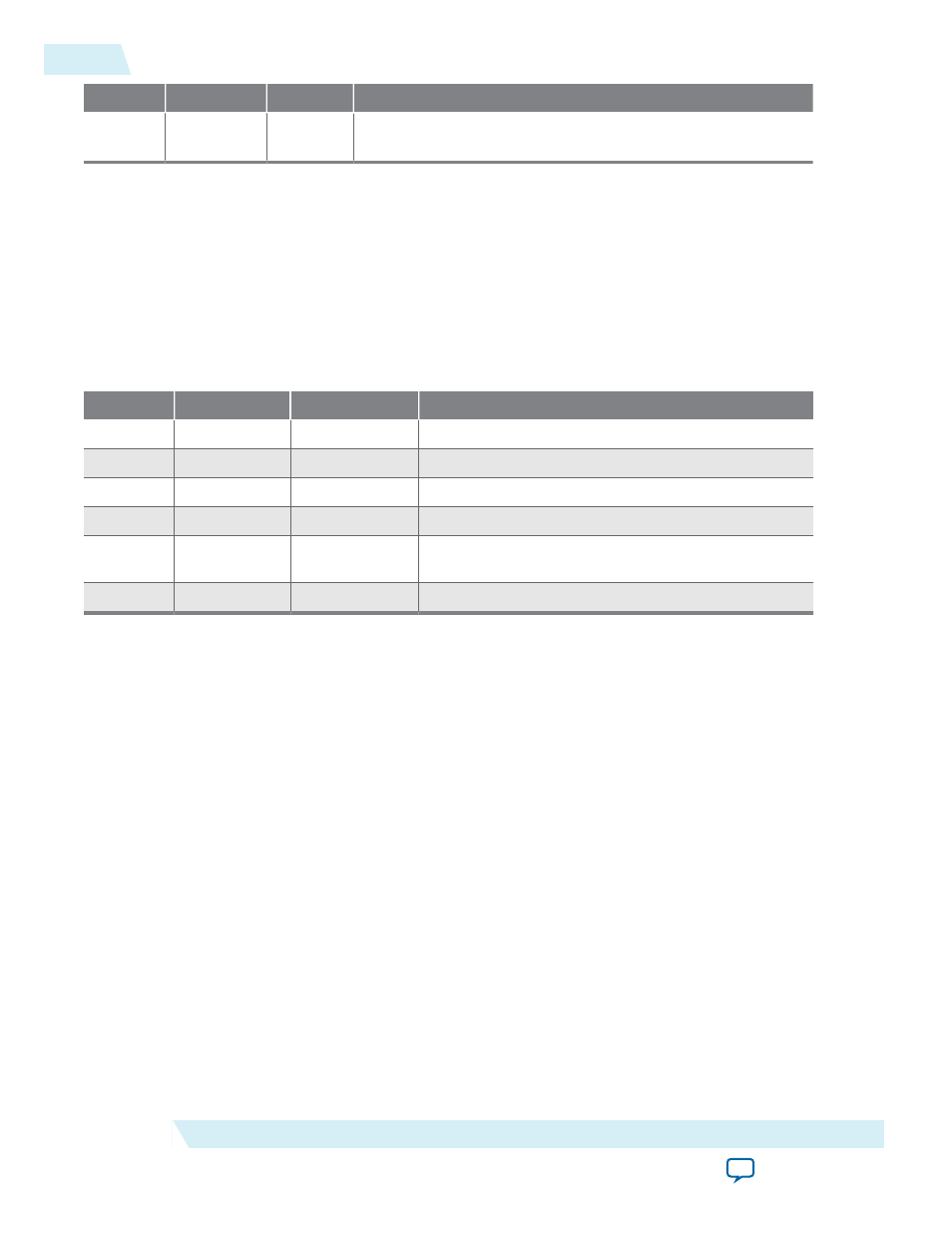
Table 7-6: Control Register Bits
Bit(s)
Name
Access
Description
0
RE
R/W
Interrupt-enable bit for read interrupts.
1
WE
R/W
Interrupt-enable bit for write interrupts.
8
RI
R
Indicates that the read interrupt is pending.
9
WI
R
Indicates that the write interrupt is pending.
10
AC
R/C
Indicates that there has been JTAG activity since the
bit was cleared. Writing 1 to
AC
clears it to 0.
[32:16]
WSPACE
R
The number of spaces available in the write FIFO.
A read from the
control
register returns the status of the read and write FIFOs. Writes to the register can
be used to enable/disable interrupts, or clear the
AC
bit.
The
RE
and
WE
bits enable interrupts for the read and write FIFOs, respectively. The
WI
and
RI
bits
indicate the status of the interrupt sources, qualified by the values of the interrupt enable bits (
WE
and
RE
).
Embedded software can examine
RI
and
WI
to determine the condition that generated the IRQ. See the
Interrupt Behavior section for further details.
The AC bit indicates that an application on the host PC has polled the JTAG UART core via the JTAG
interface. Once set, the
AC
bit remains set until it is explicitly cleared via the Avalon interface. Writing 1 to
AC
clears it. Embedded software can examine the
AC
bit to determine if a connection exists to a host PC. If
no connection exists, the software may choose to ignore the JTAG data stream. When the host PC has no
data to transfer, it can choose to poll the JTAG UART core as infrequently as once per second. Delays
caused by other host software using the JTAG download cable could cause delays of up to 10 seconds
between polls.
Interrupt Behavior
The JTAG UART core generates an interrupt when either of the individual interrupt conditions is
pending and enabled.
Interrupt behavior is of interest to device driver programmers concerned with the bandwidth perform‐
ance to the host PC. Example designs and the JTAG terminal program provided with Nios II Embedded
Design Suite (EDS) are pre-configured with optimal interrupt behavior.
7-10
Control Register
UG-01085
2014.24.07
Altera Corporation
JTAG UART Core