Timing diagrams, Timing diagrams -4 – Altera Embedded Peripherals IP User Manual
Page 245
Signal Name Width (Bits)
Direction
Description
valid
1
Input
This signal is not used by the video sync generator core
because the core always expects valid pixel data on the next
clock cycle after the
ready
signal is asserted.
sop
1
Input
Start-of-packet. This signal is asserted when the first pixel is
received.
eop
1
Input
End-of-packet. This signal is asserted when the last pixel is
received.
LCD Output Signals
rgb_out
Variable-
width
Output
Display data. The datawidth is determined by the parameter
Data Stream Bit Width.
hd
1
Output
Horizontal synchronization pulse for display.
vd
1
Output
Vertical synchronization pulse for display.
den
1
Output
This signal is asserted when the video sync generator core
outputs valid data for display.
Timing Diagrams
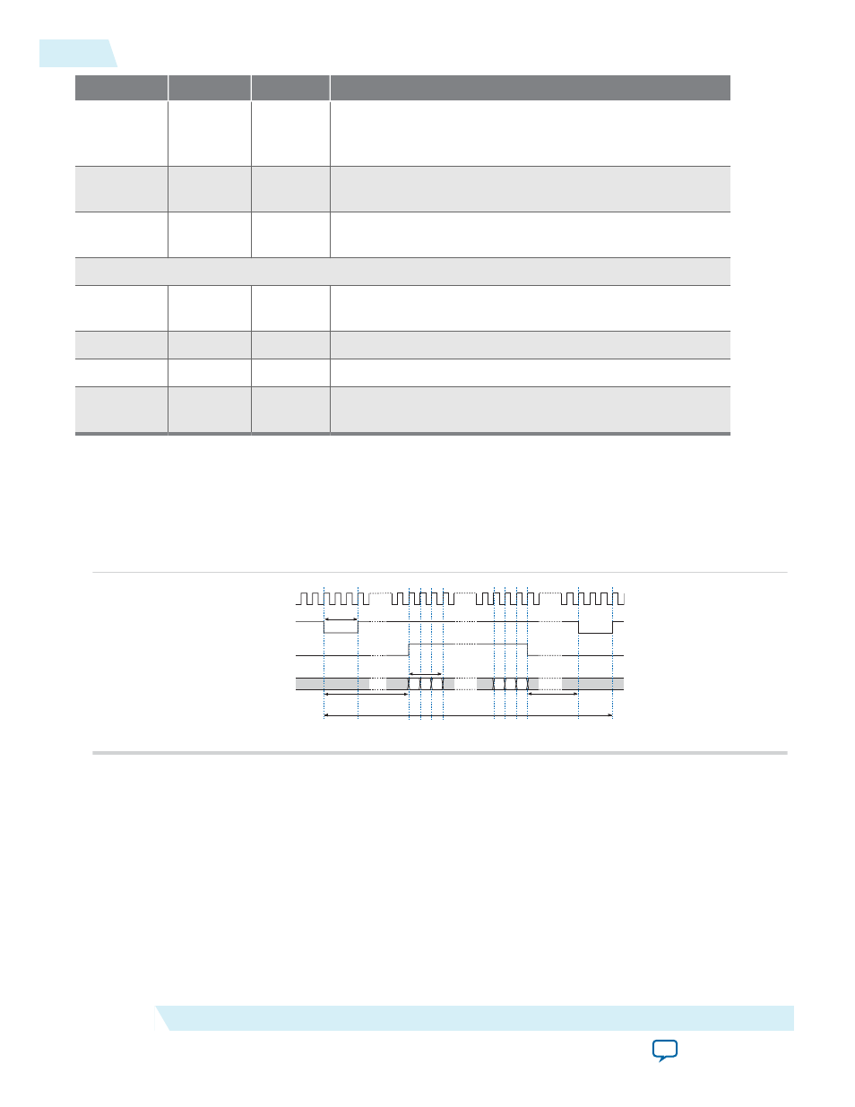
The horizontal and vertical synchronization timings are determined by the parameters setting. The table
below shows the horizontal synchronization timing when the parameters Data Stream Bit Width and
Beats Per Pixel are set to 8 and 3, respectively.
Figure 24-3: Horizontal Synchronization Timing—8 Bits DataWidth and 3 Beats Per Pixel
clk
hd
den
rgb_out
R G B
R G B
Horizontal sync pulse
Horizontal front porch
1 pixel
Horizontal blank pixels
Horizontal synchronization width
The table below sho.ws the horizontal synchronization timing when the parameters Data Stream Bit
Width and Beats Per Pixel are set to 24 and 1, respectively.
24-4
Timing Diagrams
UG-01085
2014.24.07
Altera Corporation
Video Sync Generator and Pixel Converter Cores