Parameters, Parameters -2 – Altera Embedded Peripherals IP User Manual
Page 243
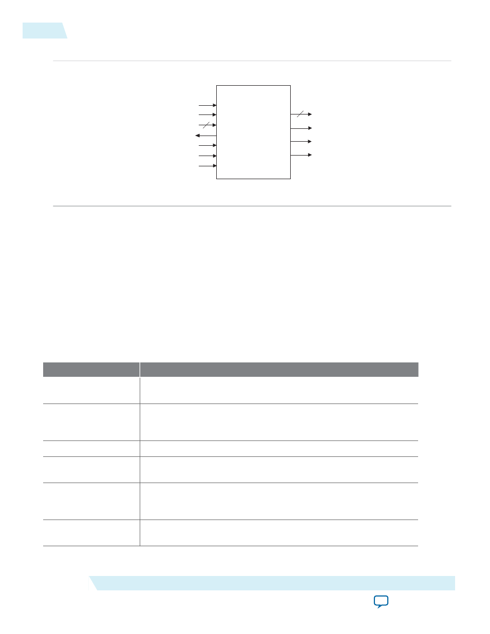
Figure 24-2: Video Sync Generator Block Diagram
clk
reset
data
ready
valid
sop
eop
rgb_out
hd
vd
den
VIDEO SYNC GENER
ATOR
You can configure various aspects of the core and its Avalon-ST interface to suit your requirements. You
can specify the data width, number of beats required to transfer each pixel and synchronization signals.
See the Parameters section for more information on the available options.
To ensure incoming pixel data is sent to the display controller with correct timing, the video sync
generator core must synchronize itself to the first pixel in a frame. The first active pixel is indicated by an
sop
pulse.
The video sync generator core expects continuous streams of pixel data at its input interface and assumes
that each incoming packet contains the correct number of pixels (Number of rows * Number of columns).
Data starvation disrupts synchronization and results in unexpected output on the display.
Parameters
Table 24-1: Video Sync Generator Parameters
Parameter Name
Description
Horizontal Sync
Pulse Pixels
The width of the h-sync pulse in number of pixels.
Total Vertical Scan
Lines
The total number of lines in one video frame. The value is the sum of the
following parameters: Number of Rows, Vertical Blank Lines, and
Vertical Front Porch Lines.
Number of Rows
The number of active scan lines in each video frame.
Horizontal Sync
Pulse Polarity
The polarity of the h-sync pulse; 0 = active low and 1 = active high.
Horizontal Front
Porch Pixels
The number of blanking pixels that follow the active pixels. During this
period, there is no data flow from the Avalon-ST sink port to the LCD
output data port.
Vertical Sync Pulse
Polarity
The polarity of the v-sync pulse; 0 = active low and 1 = active high.
24-2
Parameters
UG-01085
2014.24.07
Altera Corporation
Video Sync Generator and Pixel Converter Cores