Altera Embedded Peripherals IP User Manual
Page 158
per symbol, symbols per beat, and the width of the
channel
and
error
signals. The FIFO core performs
the endian conversion to conform to the output interface protocol.
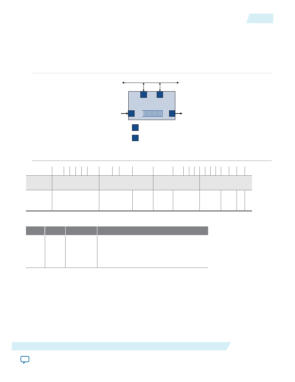
The signals that comprise the output interface are mapped into bits in the Avalon address space. If Allow
backpressure is turned on, the input interface asserts
waitrequest
to indicate that the FIFO core does
not have enough space for the transaction to complete.
Figure 16-3: FIFO with Avalon-MM Input Interface and Avalon-ST Output Interface
On -Chip FIFO
Me mory
S
S
S
S RC
Input Statu s I/F
(option a l)
Output S ta tus I/F
(option a l)
sy s te m inte rconne ct fab ric
Input Da ta
S trea ming
Output Da ta
S RC
Avalo n-S T Source
S
Avalo n-MM S la ve P ort
Offset 31
24 23
19
18 16 15 13 12
8 7
4 3 2 1 0
base +
0
Symbol 3
Symbol 2
Symbol 1
Symbol 0
base +
1
reserved
reserved
error
reserve
d
channel
reserved empt
y
E
O
P
S
O
P
Table 16-1: Memory Map
Offset
Bits
Field
Description
0
31:0
SYMBOL_0,
SYMBOL_1,
SYMBOL_
2 ..
SYMBOL_n
Packet data. The value of the Symbols per beat
parameter specifies the number of fields in this
register; Bits per symbol specifies the width of
each field.
UG-01085
2014.24.07
Avalon-MM Write Slave to Avalon-ST Source
16-3
On-Chip FIFO Memory Core
Altera Corporation