Avalon-mm interface, Configuration, Master/slave settings – Altera Embedded Peripherals IP User Manual
Page 111: Number of select (ss_n) signals, Spi clock (sclk) rate, Avalon-mm interface -5, Configuration -5, Master/slave settings -5
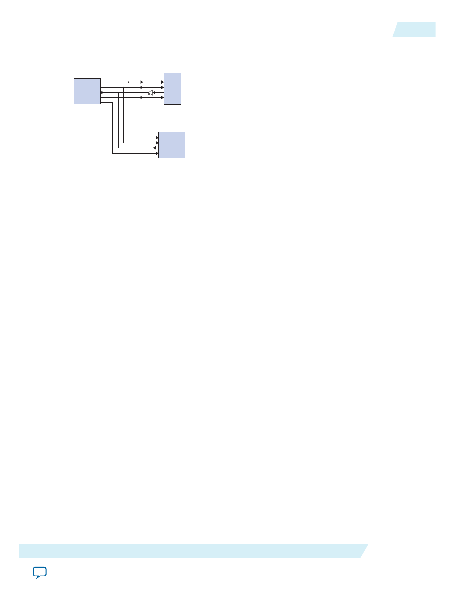
Figure 10-3: SPI Core in a Multi-Slave Environment
SPI
Master
Device
sclk
mosi
miso
ss_n0
ss_01
sclk
mosi
miso
ss_n0
SPI component
(configured as slave)
SPI
Slave
Device
SS_n
miso
mosi
sclk
Avalon-MM Interface
The SPI core’s Avalon-MM interface consists of a single Avalon-MM slave port. In addition to
fundamental slave read and write transfers, the SPI core supports Avalon-MM read and write transfers
with flow control. The flow control is disabled when:
• the option to disable flow control is turned on, or
• the option to disable flow control is turned off and the master does not support flow control.
Configuration
The following sections describe the available configuration options.
Master/Slave Settings
The designer can select either master mode or slave mode to determine the role of the SPI core. When
master mode is selected, the following options are available: Number of select (SS_n) signals, SPI clock
rate, and Specify delay.
Number of Select (SS_n) Signals
This setting specifies the number of slaves the SPI master connects to. The range is 1 to 32. The SPI master
core presents a unique
ss_n
signal for each slave.
SPI Clock (sclk) Rate
This setting determines the rate of the
sclk
signal that synchronizes data between master and slaves. The
target clock rate can be specified in units of Hz, kHz or MHz. The SPI master core uses the Avalon-MM
system clock and a clock divisor to generate
sclk
.
The actual frequency of
sclk
may not exactly match the desired target clock rate. The achievable clock
values are:
UG-01085
2014.24.07
Avalon-MM Interface
10-5
SPI Core
Altera Corporation