Setting up dma transactions, The master read and write ports, Setting up dma transactions -2 – Altera Embedded Peripherals IP User Manual
Page 233: The master read and write ports -2
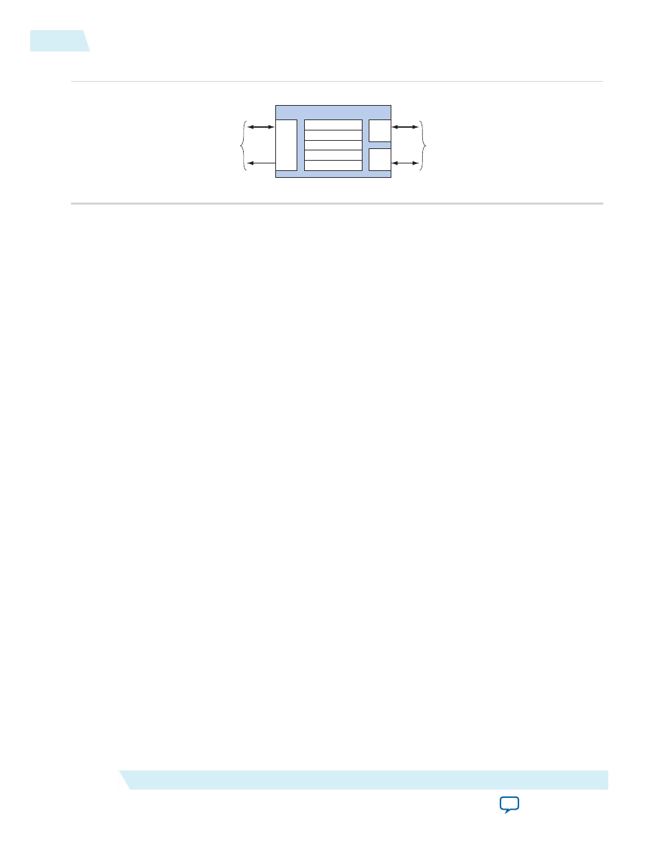
Figure 23-1: DMA Controller Block Diagram
Avalon-MM
Save Port
Addr,
data,
control
IRQ
Separate
Avalon-MM
Master Ports
Register File
status
readaddress
writeaddress
length
control
Read
Master
Port
Write
Master
Port
Control
Port
A typical DMA transaction proceeds as follows:
1. A CPU prepares the DMA controller for a transaction by writing to the control port.
2. The CPU enables the DMA controller. The DMA controller then begins transferring data without
additional intervention from the CPU. The DMA’s master read port reads data from the read address,
which may be a memory or a peripheral. The master write port writes the data to the destination
address, which can also be a memory or peripheral. A shallow FIFO buffers data between the read and
write ports.
3. The DMA transaction ends when a specified number of bytes are transferred (a fixed-length transac‐
tion) or an end-of-packet signal is asserted by either the sender or receiver (a variable-length transac‐
tion). At the end of the transaction, the DMA controller generates an interrupt request (IRQ) if it was
configured by the CPU to do so.
4. During or after the transaction, the CPU can determine if a transaction is in progress, or if the transac‐
tion ended (and how) by examining the DMA controller’s
status
register.
Setting Up DMA Transactions
An Avalon-MM master peripheral sets up and initiates DMA transactions by writing to registers via the
control port. The Avalon-MM master programs the DMA engine using byte addresses which are byte
aligned. The master peripheral configures the following options:
• Read (source) address location
• Write (destination) address location
• Size of the individual transfers: Byte (8-bit), halfword (16-bit), word (32-bit), doubleword (64-bit) or
quadword (128-bit)
• Enable interrupt upon end of transaction
• Enable source or destination to end the DMA transaction with end-of-packet signal
• Specify whether source and destination are memory or peripheral
The master peripheral then sets a bit in the
control
register to initiate the DMA transaction.
The Master Read and Write Ports
The DMA controller reads data from the source address through the master read port, and then writes to
the destination address through the master write port. You program the DMA controller using byte
addresses. Read and write start addresses should be aligned to the transfer size. For example, to transfer
data words, if the start address is 0, the address will increment to 4, 8, and 12. For heterogeneous systems
where a number of different slave devices are of different widths, the data width for read and write
masters matches the width of the widest data-width slave addressed by either the read or the write master.
For bursting transfers, the burst length is set to the DMA transaction length with the appropriate unit
conversion. For example, if a 32-bit data width DMA is programmed for a word transfer of 64 bytes, the
23-2
Setting Up DMA Transactions
UG-01085
2014.24.07
Altera Corporation
DMA Controller Core