Altera Embedded Peripherals IP User Manual
Page 230
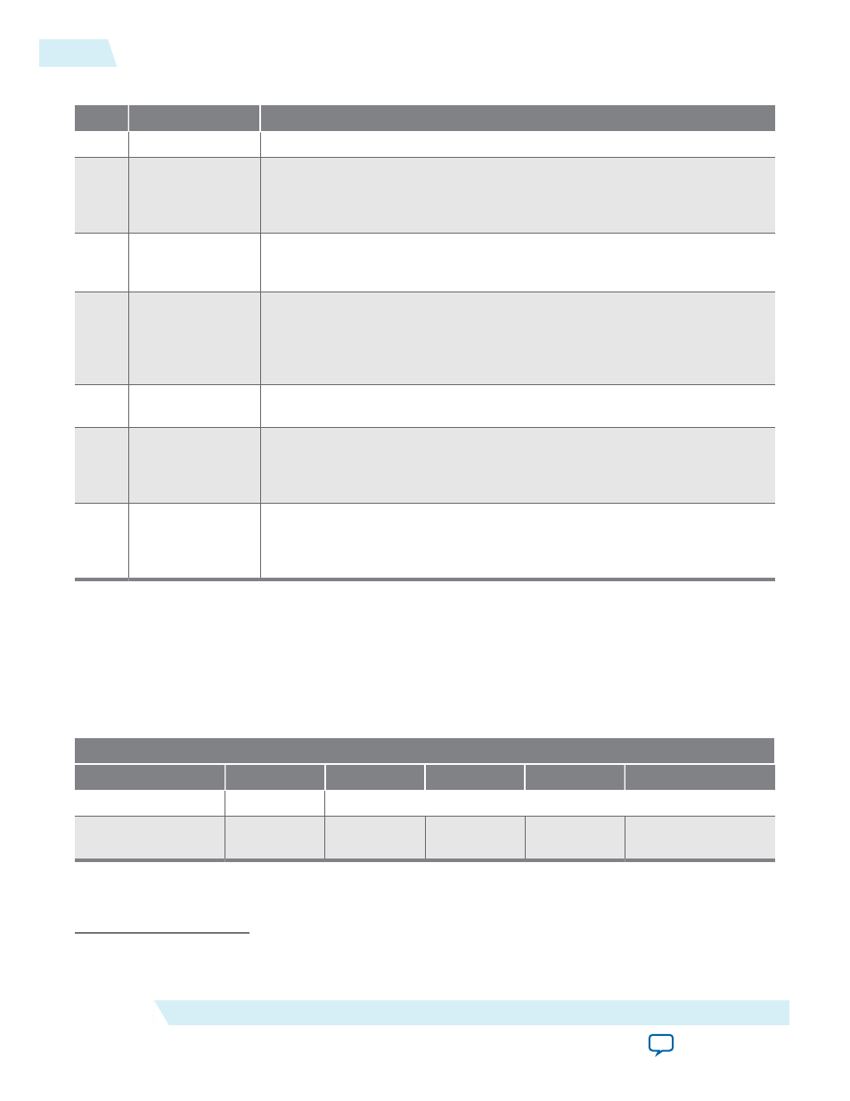
Table 22-6: Control Register Bit Definition
Bit
Name
Description
31:10
N/A
5
Stop Descriptors
Setting this bit will stop the SGDMA dispatcher from issuing more descriptors
to the read or write masters. Read the stopped status register to determine
when the dispatcher has stopped issuing commands and the read and write
masters are idle.
4
Global Interrupt
Enable Mask
Setting this bit will allow interrupts to propagate to the interrupt sender port.
This mask occurs after the register logic so that interrupts are not missed when
the mask is disabled.
3
Stop on Early
Termination
Setting this bit will stop the SGDMA from issuing out more read/write
commands to the master modules if the write master attempts to write more
data than the user specifies in the length field for packet transactions. The
length field is used to limit how much data can be sent and is always enabled
for packet based writes.
2
Stop on Error
Setting this bit will stop the SGDMA from issuing more read/write commands
to the master modules if an error enters the write master module sink port.
1
Reset Dispatcher
Setting this bit will reset the registers and FIFOs of the dispatcher and master
modules. Since resets can take multiple clock cycles to complete due to
transfers being in flight on the fabric you should read the resetting status
register to determine when a full reset cycle has completed.
0
Stop Dispatcher
Setting this bit will stop the SGDMA in the middle of a transaction. If a read or
write operation is occurring then the access will be allowed to complete. Read
the stopped status register to determine when the SGDMA has stopped. After
reset the dispatcher core defaults to a start mode of operation.
The response slave port of mSGDMA contains registers providing information of the executed transac‐
tion. This register map is only applicable when the response mode is enabled and set to MM. Also when
the response port is enabled it needs to have responses read because it buffers responses. When it is setup
as a memory-mapped slave port, reading byte offset 0x7 pops the response. If the response FIFO becomes
full the dispatcher stops issuing transfer commands to the read and write masters. The following
paragraph describes the registers definition.
Table 22-7: Response Registers Map
Byte Lanes
Offset
Access
3
2
1
0
0x0
Read
Actual Bytes Transferred[31:0]
0x4
Read
(3)
Early
Termination
(4)
Error[7:0]
(3)
Reading from byte 7 pops the response FIFO.
(4)
Early Termination is a single bit located at bit 8 of offset 0x4.
22-14
Control Register
UG-01085
2014.24.07
Altera Corporation
Altera Modular Scatter-Gather DMA