Rockwell Automation 21G PowerFlex 750-Series AC Drives Programming Manual User Manual
Page 94
94
Rockwell Automation Publication 750-PM001J-EN-P - October 2014
Chapter 3
Drive Port 0 Parameters
DR
IV
E CFG
Bra
king F
ea
tures
372
373
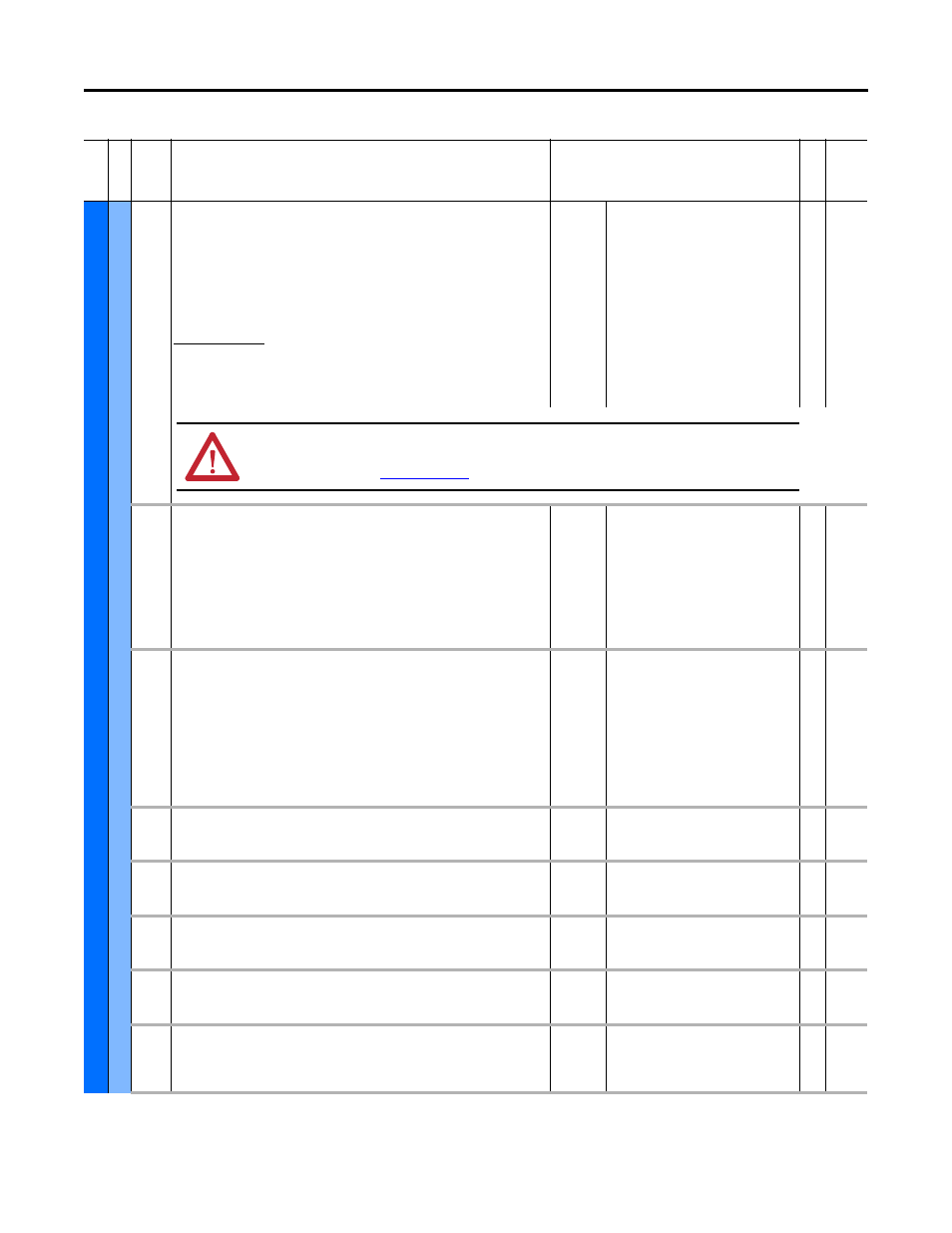
Bus Reg Mode A
Bus Reg Mode B
Bus Regulation Mode A, B
Method and sequence of the DC bus regulator voltage. Choices are dynamic brake,
frequency adjust or both. Sequence is determined by programming or digital input to
the terminal block. Using options 1, 3, or 4, may result in extended decel times.
Typically, only P372 [Bus Reg Mode A] is used. P373 [Bus Reg Mode B] is only used when
P187 [DI PwrLoss ModeB] is programmed and its corresponding input is high.
Dynamic Brake Setup
If a dynamic brake resistor is connected to the drive, both of these parameters must be
set to either option 2, 3 or 4.
When using any of the dynamic braking settings increase P426 [Regen Power Lmt] from
its default setting of 50%. A setting of 200% will result in more effective braking.
Default:
Options:
1 = “Adjust Freq”
4 = “Both-Frq 1st”
0 = “Disabled”
1 = “Adjust Freq”
2 = “Dyn Brake”
3 = “Both DB 1st”
4 = “Both Frq 1st”
RW 32-bit
Integer
374
Bus Reg Lvl Cfg
Bus Regulation Level Configuration
Selects the reference used to determine the bus voltage regulation level for the bus
voltage regulator and the reference used for the dynamic brake.
“Bus Memory” (0) – References are determined based on P12 [DC Bus Memory].
“BusReg Level” (1) – References are determined based on the voltage set in the bus
regulator level parameter P375 [Bus Reg Level]. If coordinated operation of the dynamic
brakes of a common bus system is desired, use this selection and set the P375 [Bus Reg
Level] to coordinate the brake operation of the common bus drives.
Default:
Options:
0 = “Bus Memory”
0 = “Bus Memory”
1 = “BusReg Level”
RW 32-bit
Integer
375
Bus Reg Level
Bus Regulation Level
Sets the “turn-on” bus voltage level for the bus voltage regulator and the dynamic
brake.
Units:
Default:
Min/Max:
V DC
P20 < 252V DC: 375
P20 = 252…503V DC: 750
P20 = 504…629V DC: 937
P20 > 629V DC: 1076
P20 < 252V DC: 375/389
P20 = 252…503V DC: 750/779
P20 = 504…629V DC: 937/974
P20 > 629V DC: 1076/1118
RW Real
376
Bus Limit Kp
Bus Limit Proportional Gain
Not functional when any of the FV motor control modes are selected.
Units:
Default:
Min/Max:
A/V
1170.0
0.0 / 1000000.0
RW Real
377
Bus Limit Kd
Bus Limit Derivative Gain
Not functional when any of the FV motor control modes are selected.
Units:
Default:
Min/Max:
Secs
152.0
0.0 / 1000000.0
RW Real
378
Bus Limit ACR Ki
Bus Limit Active Current Regulator Integral Gain
Not functional when any of the FV motor control modes are selected.
Default:
Min/Max:
2045.0
0.0 / 50000.0
RW Real
379
Bus Limit ACR Kp
Bus Limit Active Current Regulator Proportional Gain
Not functional when any of the FV motor control modes are selected.
Units:
Default:
Min/Max:
Hz/A
524.0
0.0 / 100000.0
RW Real
380
Bus Reg Ki
Bus Regulator Integral Gain
Integral gain for the bus voltage regulator. Sets the responsiveness of the bus voltage
regulator.
Default:
Min/Max:
100.000
0.000 / 65535.000
RW Real
Fi
le
Grou
p
No.
Display Name
Full Name
Description
Values
Re
ad
-W
ri
te
Da
ta
T
ype
ATTENTION: The drive does not offer protection for externally-mounted brake resistors. A risk of fire exists if external
braking resistors are not protected. External resistor packages must be self-protected from over-temperature or the
protective circuit shown in
(or equivalent) must be supplied.