Rockwell Automation 21G PowerFlex 750-Series AC Drives Programming Manual User Manual
Page 168
168
Rockwell Automation Publication 750-PM001J-EN-P - October 2014
Chapter 3
Drive Port 0 Parameters
DIA
G
NOSTICS
Fa
u
lt
/A
la
rm
In
fo
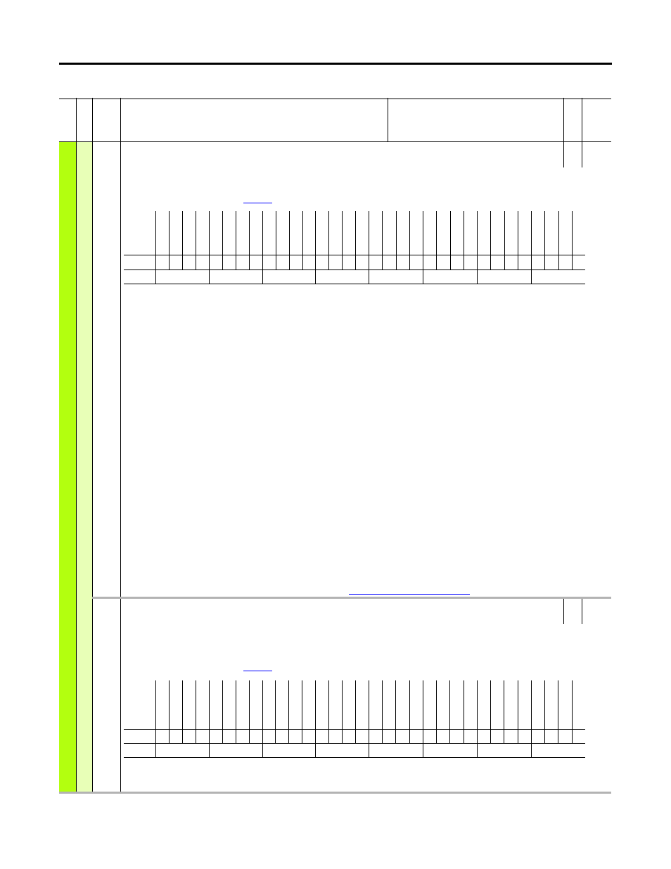
962
AlarmA at Fault
Alarm A at Fault
RO
32-bit
Integer
Captures and displays P959 [Alarm Status A] at the time of the last fault.
For some alarms, the value captured in this parameter may not match peak/low at time of fault due to data latency.
For details on alarms and faults, refer to
Bit 0 “Power Loss” – A Power Loss exception has been issued.
Bit 1 “UnderVoltage” – An Under Voltage exception has been issued.
Bit 2 “Motor OL” – An excessive motor load exists.
Bit 4 “InPhaseLoss” – Input Phase Loss exception has been issued.
Bit 5 “OutPhaseLoss” – Output Phase Loss exception has been issued.
Bit 6 “Decel Inhib” – The drive is being Inhibited from decelerating to the commanded speed.
Bit 7 “Shear Pin 1” – Value set in P436 [Shear Pin1 Level] has been exceeded.
Bit 8 “Shear Pin 2” – Value set in P439 [Shear Pin2 Level] has been exceeded.
Bit 9 “PriFdbkLoss” – When set, indicates that the device selected as the primary velocity feedback source has reported a device failure. P125 [Pri Vel Fdbk Sel]
selects the device used as the primary velocity feedback source. The primary feedback device supplies motor speed feedback if the Automatic Tach Switchover
option is either disabled or has not switched to the alternate feedback device. In order to report this condition as an alarm, the feedback loss configuration
parameter for the primary feedback device must be configured for “Alarm.”
Bit 10 “AltFdbkLoss” – When set, indicates that the device selected as the alternate velocity feedback source has reported a device failure. P128 [Alt Vel Fdbk Sel]
selects the device used as the alternate velocity feedback source. The alternate feedback device supplies motor speed feedback if the Automatic Tach Switchover
option is enabled and the primary feedback device has failed. In order to report this condition as an alarm, the feedback loss configuration parameter for the
alternate feedback device must be configured for “Alarm.”
Bit 11 “AuxFdbkLoss” – When set, indicates that the device selected as the auxiliary velocity feedback source has reported a device failure. P132 [Aux Vel Fdbk Sel]
selects the device used as the auxiliary velocity feedback source. The auxiliary feedback device can be used to supply motor speed reference. In order to report this
condition as an alarm, the feedback loss configuration parameter for the auxiliary feedback device must be configured for “Alarm.”
Bit 12 “PosFdbkLoss” – When set, indicates that the device selected as the position feedback source has reported a device failure. P135 [Psn Fdbk Sel] selects the
device used as the position feedback source. Position feedback is used for position control applications. It can be the same device used for velocity feedback or
position feedback can be supplied by a separate device. In order to report this condition as an alarm, the feedback loss configuration parameter for the position
feedback device must be configured for “Alarm.”
Bit 14 “GndWarning” – Value set in P467 [Ground Warn Lvl] has been exceeded.
Bit 15 “Task Overrun” – System resource utilization has been exceeded. See
System Resource Allocation on page 311
for details.
963
AlarmB at Fault
Alarm B at Fault
RO
32-bit
Integer
Captures and displays P960 [Alarm Status B] at the time of the last fault.
See parameter 960 [Alarm Status B] for bit descriptions.
For some alarms, the value captured in this parameter may not match peak/low at time of fault due to data latency.
For details on alarms and faults, refer to
Fi
le
Grou
p
No.
Display Name
Full Name
Description
Values
Re
ad
-W
ri
te
Da
ta
T
ype
Options
Re
ser
ve
d
Re
ser
ve
d
Re
ser
ve
d
Re
ser
ve
d
Re
ser
ve
d
Re
ser
ve
d
Re
ser
ve
d
Re
ser
ve
d
Re
ser
ve
d
Re
ser
ve
d
Re
ser
ve
d
Re
ser
ve
d
Re
ser
ve
d
Re
ser
ve
d
Re
ser
ve
d
Re
ser
ve
d
Ta
sk
O
verrun
Gn
d W
ar
nin
g
Re
ser
ve
d
Po
sF
dbkL
oss
Au
xF
dbkL
oss
AltF
dbkL
oss
Pr
iF
dbkL
oss
Shear Pin
2
Shear Pin
1
De
ce
l I
nh
ib
O
utPhaseL
oss
In
PhaseL
oss
Lo
ad
Lo
ss
Mot
or OL
Un
derV
ol
ta
ge
Po
w
er
L
os
s
Default
0
0
0
0
0
0
0
0
0
0
0
0
0
0
0
0
0
0
0
0
0
0
0
0
0
0
0
0
0
0
0
0
Bit
31 30 29 28 27 26 25 24 23 22 21 20 19 18 17 16 15 14 13 12 11 10 9
8
7
6
5
4
3
2
1
0
0 = Condition False
1 = Condition True
Options
Re
se
rv
ed
Re
se
rv
ed
Re
se
rv
ed
Re
se
rv
ed
Re
se
rv
ed
Re
se
rv
ed
Re
se
rv
ed
Re
se
rv
ed
Re
se
rv
ed
Re
se
rv
ed
Re
se
rv
ed
Re
se
rv
ed
Re
se
rv
ed
Re
se
rv
ed
Re
se
rv
ed
Re
se
rv
ed
DB Res
OT
N-1
O
per
at
e
PumpO
ff Alrm
OW
Ala
rm
T
O
OW
L
ev
el
Gnd
W
ar
ning
No
t Home
S
et
Homi
ng A
ct
v
Pr
of
ile A
ct
v
(1)
(1) 755 drives only.
PWMF
rq
Red
uc
Cu
rL
m
t R
ed
uc
Dr
iv
e O
L
Star
tO
nP
wrUp
Wa
ki
ng
Heatsi
nk O
T
IGB
T O
T
Default
0
0
0
0
0
0
0
0
0
0
0
0
0
0
0
0
0
0
0
0
0
0
0
0
0
0
0
0
0
0
0
0
Bit
31 30 29 28 27 26 25 24 23 22 21 20 19 18 17 16 15 14 13 12 11 10 9
8
7
6
5
4
3
2
1
0
0 = Condition False
1 = Condition True