Dual incremental encoder module parameters – Rockwell Automation 21G PowerFlex 750-Series AC Drives Programming Manual User Manual
Page 269
Rockwell Automation Publication 750-PM001J-EN-P - October 2014
269
Embedded Feature and Option Module Parameters
Chapter 5
Dual Incremental Encoder
Module Parameters
Sing
le Incr
emen
tal En
co
der
7
Phase Loss Count
Phase Loss Count
Displays the total number of encoder errors detected by the encoder card every 1
millisecond sample interval. These values are reset to zero every 1 millisecond.
Diagnostic Items are available for the encoder that show the errors counted over 8
milliseconds as well as the peak error values. The peak values are reset when the drive
faults are cleared.
Default:
Min/Max:
0
0 / 127
RO
Real
8
Quad Loss Count
Displays the total number of encoder errors detected by the encoder card every 1
millisecond sample interval. These values are reset to zero every 1 millisecond.
Diagnostic Items are available for the encoder that show the errors counted over 8
milliseconds as well as the peak error values. The peak values are reset when the drive
faults are cleared.
Default:
Min/Max:
0
0 / 15
RO
Real
Fi
le
Grou
p
No.
Display Name
Full Name
Description
Values
Re
ad
-W
ri
te
Da
ta
T
ype
Fil
e
Gr
oup
No.
Display Name
Full Name
Description
Values
Read-W
ri
te
Da
ta
T
yp
e
D
ua
l Incremental Enco
der
Encoder 0
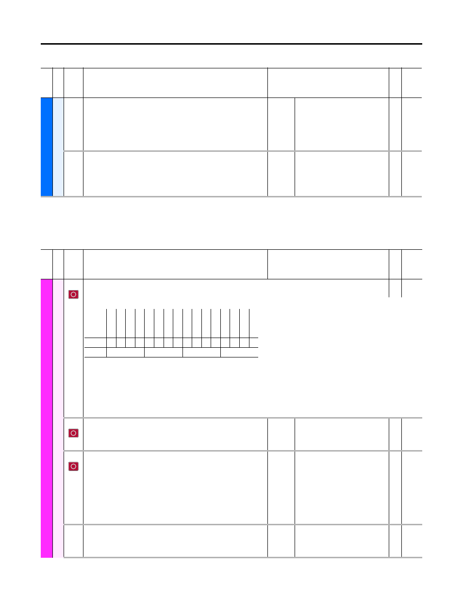
1
Enc 0 Cfg
Encoder 0 Configure
RW 16-bit
Integer
Configures the position direction, speed calculation method, signal type and active encoder channels used for Encoder 0 (primary encoder).
Bit 0 “Z Channel Enbl” – Configures the Channel Z to be used and monitored for Phase Loss. A value of 0 = the Z channel will be ignored.
Bit 1 “A Chan Only” – Configures the module to use only the A channel, and ignore the B channel. In this mode, direction cannot be determined, and the position
counter will always count up.
Bit 2 “Edge Mode” – Configure the module to use AB edge time data for speed calculation rather than accumulated count.
Bit 4 “Single Ended” – Configure when the A Quad B encoder has single ended signals. In this mode, Phase Loss detection is disabled.
0 = Differential, 1 = Single Ended
Bit 5 “Direction” – Inverts the feedback count up/down associated with a given rotation direction internally. 1 = invert, 0 = do not invert
2
Enc 0 PPR
Encoder 0 Pulses Per Revolution
Configures the encoder module's primary input (Encoder 0) for the Pulses Per Revolution
(Encoder Lines) of the A Quad B Encoder.
Default:
Min/Max:
1024
2 / 20000
RW 32-bit
Integer
3
Enc 0 FB Lss Cfg
Encoder 0 Feedback Loss Configure
Configures how the drive reacts to an error status condition for Encoder 0 (primary
encoder).
“Ignore” (0) – No action is taken.
“Alarm” (1) – Type 1 alarm indicated.
“Flt Minor” (2) – Minor fault indicated. If running, drive continues to run.
Enable with P950 [Minor Flt Cfg]. If not enabled, acts like a major fault.
“FltCoastStop” (3) – Major fault indicated. Coast to Stop.
Default:
Options:
3 = “FltCoastStop”
0 = “Ignore”
1 = “Alarm”
2 = “Flt Minor”
3 = “FltCoastStop”
RW 32-bit
Integer
4
Enc 0 FB
Encoder 0 Feedback
Displays the position feedback value of Encoder 0 (primary encoder). This should be
used as a source for the main control (Port 0) Feedback Select.
Default:
Min/Max:
0
–/+2147483647
RO
32-bit
Integer
Options
Re
ser
ve
d
Re
ser
ve
d
Re
ser
ve
d
Re
ser
ve
d
Re
ser
ve
d
Re
ser
ve
d
Re
ser
ve
d
Re
ser
ve
d
Re
ser
ve
d
Re
ser
ve
d
Di
re
ct
io
n
Single E
nded
Re
ser
ve
d
Ed
ge
Mode
A Chan
O
nly
Z Ch
an
E
nbl
Default
0
0
0
0
0
0
0
0
0
0
0
0
0
0
0
0
Bit
15 14 13 12 11 10 9
8
7
6
5
4
3
2
1
0
0 = Condition False
1 = Condition True