Parameter configuration – Rockwell Automation 21G PowerFlex 750-Series AC Drives Programming Manual User Manual
Page 491
Rockwell Automation Publication 750-PM001J-EN-P - October 2014
491
Using DeviceLogix
Appendix C
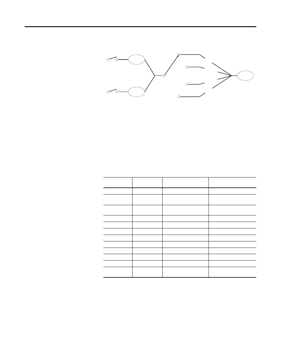
Figure 89 - Two Input Four Position Selector Switch Logic Map
Discrete Inputs in the Drive are used for Inputs 1 and Input 2. Output A, B, C,
and D are linked to DeviceLogix Scratchpad Registers. This allows further
flexibility to modify the values of these outputs.
The resulting output can be linked to a parameter and used in supporting drive
applications, such as configuring multiple preset speeds and point to point
positioning. In this example, it controls Preset Speed 1.
Parameter Configuration
The following parameters are configured for this example:
Port Parameter
No.
Parameter
Value
Description
14.1
DLX Out 01
Port 0:Preset Speed 1
14.33
DLX DIP 1
Port 4: Dig In Status.Input 1
Digital input 1 from Selector
Switch
14.34
DLX DIP 2
Port 4: Dig In Status.Input 2
Digital input 2 from Selector
Switch
14.17
DLX In 01
Port 14: DLX Real SP1
Output A
14.18
DLX In 02
Port 14: DLX Real SP2
Output B
14.19
DLX In 03
Port 14: DLX Real SP3
Output C
14.20
DLX In 04
Port 14: DLX Real SP4
Output D
14.54
DLX Real SP1
75.00
Output A Preset Speed
14.55
DLX Real SP2
85.00
Output B Preset Speed
14.56
DLX Real SP3
95.00
Output C Preset Speed
14.57
DLX Real SP4
105.00
Output D Preset Speed
0.571
Preset Speed 1
varies
Resulting output from Selector
Switch
Digital Input 1
DLX
DIP 1
Digital Input 2
DLX
DIP 2
DLX
Out 1
00
01
10
11
Output A
Output B
Output C
Output D