Functional block programming, Figure 92 - control circuit – Rockwell Automation 21G PowerFlex 750-Series AC Drives Programming Manual User Manual
Page 498
498
Rockwell Automation Publication 750-PM001J-EN-P - October 2014
Appendix C
Using DeviceLogix
Functional Block Programming
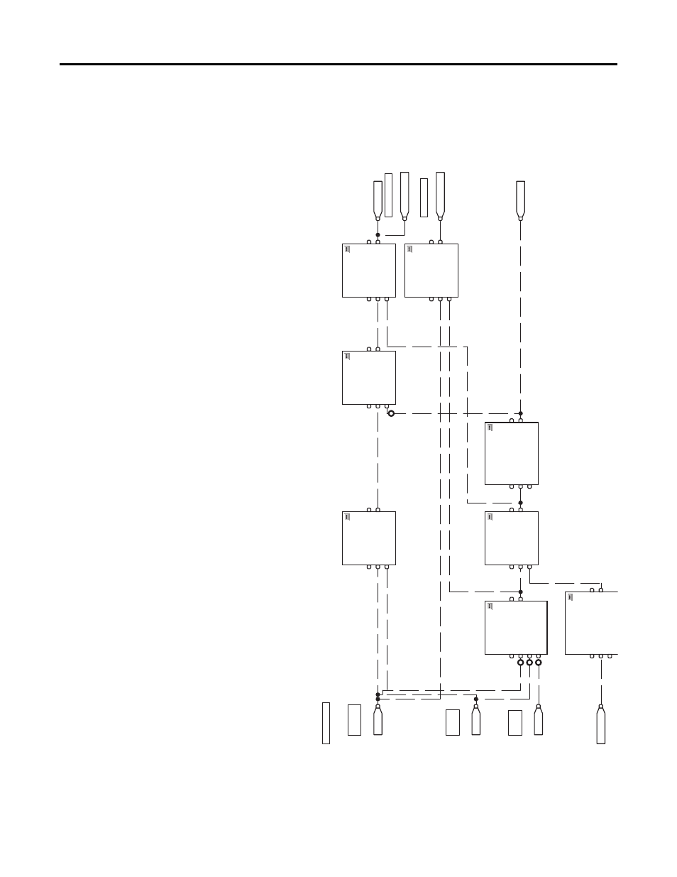
This example consists of 16 blocks that are shown in the following figure.
Figure 92 - Control Circuit
St
ar
t
Sp
dR
ef
S
el
1
2B
AN
D
B
ool
ea
n A
n
d
En
ab
le
In
In
1
In
2
In
3
6B
AN
D
B
ool
ea
n A
n
d
En
ab
le
In
In
1
In
2
7S
ET
D
Se
t D
om
ina
nt
En
ab
le
In
Se
t
Re
se
t
DI
P 2
DI
P 1
DI
P 3
A
cti
ve
St
op
is
mo
me
n
ta
ri
ly
as
se
rt
ed
( 2
se
cs
)
5P
UL
R
Pu
ls
e T
ime
r w
ith
R
es
et
En
ab
le
In
Ti
me
rE
n
ab
le
Re
se
t
4B
AN
D
B
ool
ea
n A
n
d
En
ab
le
In
In
1
In
2
8S
ET
D
Se
t D
om
ina
nt
En
ab
le
In
Se
t
Re
se
t
St
op
1B
OR
B
ool
ea
n O
r
En
ab
le
In
In
1
In
2
Ru
n a
t Hi
gh
Ra
te
Sp
dR
ef
S
el
0
Ru
n a
t No
rm
al
R
at
e
Cr
itic
al
H
ig
h
Le
ve
l S
en
sor
Hi
gh Lev
el
Se
n
so
r
Lo
w
Le
ve
l
Se
n
so
r
Mi
ni
m
um
P
ump
Ti
me
3T
O
NR
Ti
me
r O
n
D
el
ay
w
ith
R
es
et
En
ab
le
In
Ti
m
er
En
ab
le
Re
se
t
CO
NT
R
OL
CI
RCUI
T
This manual is related to the following products: