Example 3: diverter operation, Parameter configuration, Functional block programming – Rockwell Automation 21G PowerFlex 750-Series AC Drives Programming Manual User Manual
Page 495
Rockwell Automation Publication 750-PM001J-EN-P - October 2014
495
Using DeviceLogix
Appendix C
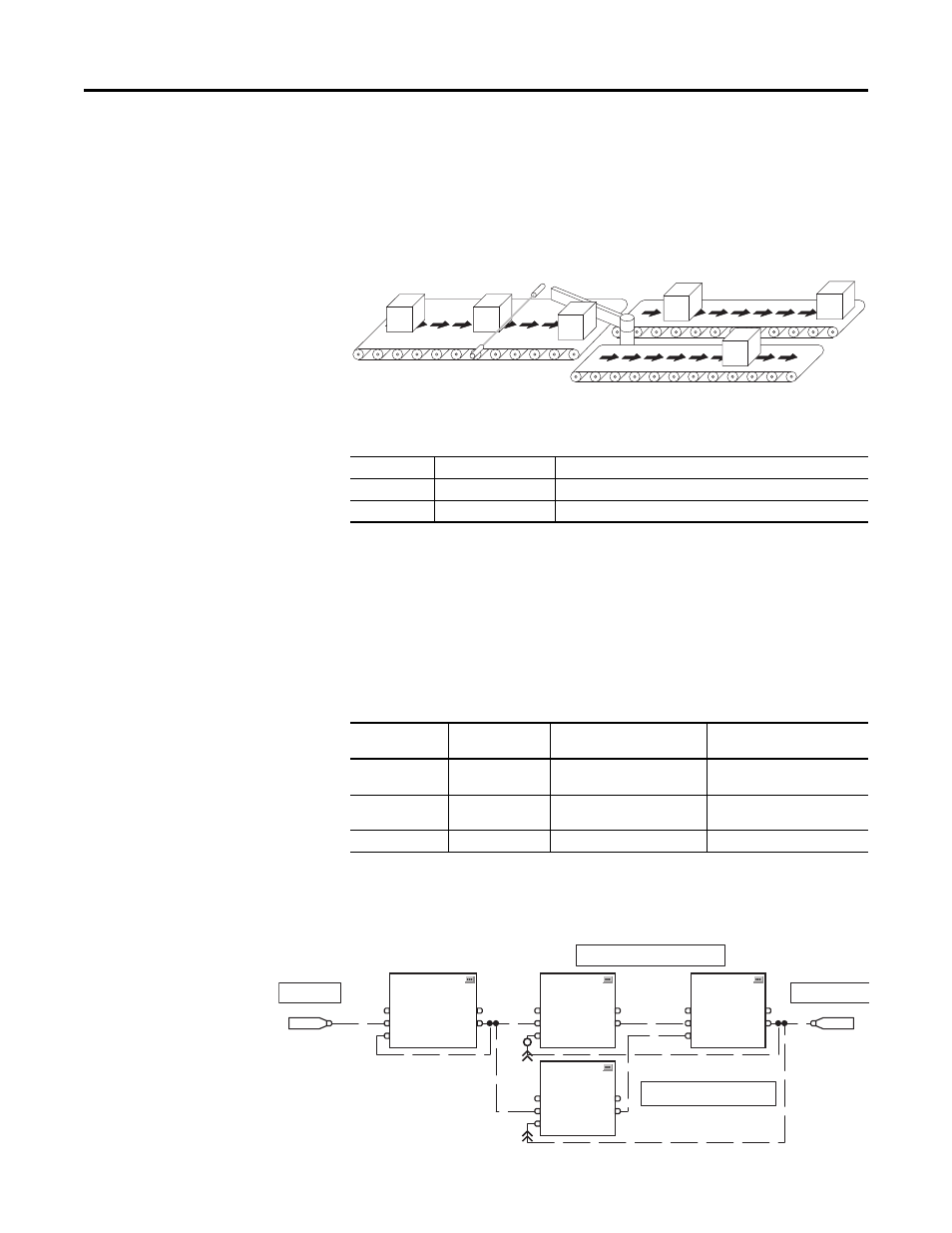
Example 3: Diverter Operation
This example demonstrates basic control logic to operate a diverter in a conveyor
system. The diverter directs parts from an upstream conveyor to one of two
downstream conveyors. It alternately sends ‘x’ parts down each downstream
conveyor.
The application consists of the following discrete I/O:
Example logic requirements:
·
If Part Present Sensor is ON, then increment the parts counter
·
If parts counter preset is reached, reset the counter and alternately set or reset
the Diverter Actuator
Parameter Configuration
The following parameters are configured for this example:
Functional Block Programming
This example consists of 4 blocks that are shown in the following figure.
Type
Name
Description
Inputs
Part Present Sensor
Identifies that a part is present
Outputs
Diverter Actuator
Controls the diverter actuator to direct the flow of parts
Port Parameter
No.
Parameter
Value
Description
4.20
TO0 Select
Port 14: DLX DigOut Sts2.DLX
DOPSts0
Output on I/O module in Port 4
14.33
DLX DIP 1
Port 4: Dig In Status.Input 1
Part Present Sensor input
(I/O module in Port 4)
14.51
DLX DigOut Sts2
Diverter Actuator output
Upstream Conveyor
Downstream Conveyor
Sensor
Diverter
DIP 1
0
Parts Counter
1 CTU
Count Up
EnableIn
CUEnable
Reset
1
0
DOP 1
0
Part Present
Photoeye
Output to control
the diverter
Flip-Flop circuit
1st time ON / 2nd time OFF on so on
Because loop-back is performed,
">>" is used to determine order
2 BAND
Boolean And
EnableIn
In1
In2
1
0
4 SETD
Set Dominant
EnableIn
Set
Reset
1
0
3 BAND
Boolean And
EnableIn
In1
In2
1
0